Quantification of hydrophobic and hydrophilic properties of materials

Inactive Publication Date: 2009-03-12
INTERUNIVERSITAIR MICRO ELECTRONICS CENT (IMEC VZW) +1
View PDF1 Cites 5 Cited by
  • Summary
  • Abstract
  • Description
  • Claims
  • Application Information

AI Technical Summary

Benefits of technology

[0007]A good method for quantifying hydrophilic and/or hydrophobic properties of a material is provided. The method can be performed quickly, is easily applicable and is non-destructive. The method can be used for

Problems solved by technology

A critical issue in integration of porous materials, such as e.g. low-k materials, in semiconductor processing is the degradation of their properties, e.g. their dielectric properties, during plasma etching and/or resist stripping.
Because of this, porous dielectrics are very sensitive to plasma induced damage during processing steps such as e.g. etching and stripping.
A damage mechanism which may occur is the replacement of hydrophobic methyl groups by hydrophilic OH groups.
For example, in carbon doped silica (SiOC) a Si—CH3 bond may be broken and carb

Method used


Image

  • Quantification of hydrophobic and hydrophilic properties of materials
  • Quantification of hydrophobic and hydrophilic properties of materials
  • Quantification of hydrophobic and hydrophilic properties of materials

Examples


example 1

Monitoring of Plasma Damage after O2 / Cl2 Plasma Processing Using a He Plasma to Create Oxygen Radicals during De-Chucking Step (ex-situ)

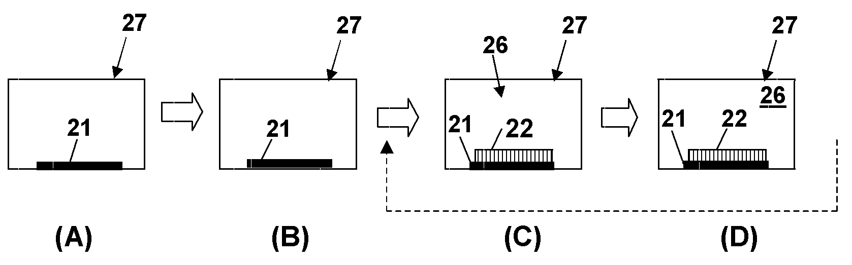
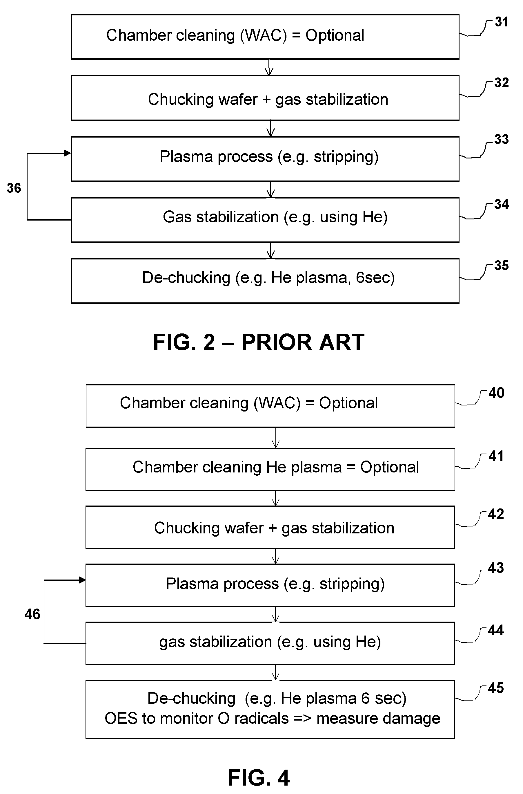
[0072]Experiments were performed in an industrial plasma etch chamber 20 (LAM Versys 2300 STAR equipped with OES analyzer with spectral resolution of 2.5 nm). Wafer temperature during all the experiments was 30° C. Several plasmas were used in the whole processing sequence. An O2 / SF6 plasma was used for waferless auto-cleaning (WAC) of plasma chamber sidewalls 23 and O2 / Cl2 was used to simulate photoresist removal on the low-k material. A He plasma was used for removing the wafer 22 from the chuck 21 as well as for simultaneously releasing radicals from adsorbed water to the low-k material and thus to simultaneously monitor (or evaluate) plasma damage caused by the O2 / Cl2 plasma to the low-k material.

[0073]The low-k material used in these experiments was porous carbon doped silica (BDIIx® obtainable from Applied Materials) deposited by Plasma Enhanc...

example 2

Correlation of FTIR and WEP with Chemiluminescence to Provide Quantitative Data about Degree of Plasma Damage

[0075]Two alternative techniques were used to monitor plasma damage due to O2 / Cl2 plasma exposure to a porous low-k material, i.e. Fourier Transform InfraRed (FTIR) and water based ellipsometric porosimetry (WEP).

[0076]To monitor hydrophilic OH groups by FTIR the absorbance of silanol groups was monitored (see FIG. 9, (A)). Taking into account the fact that the degree of plasma damage is proportional to absorbance of —OH groups incorporated into the bulk of low-k materials, the degree of plasma damage can be evaluated. The absorbance of a pristine sample (non-damaged low-k material) was monitored first and the amplitude of OH groups is close to zero and intensity of the C—H peak is the highest one (corresponding to hydrophobic Si—CH3 groups). This can be determined by FTIR, as mentioned before. Curve “Ref.” in FIG. 9, (A) shows a reference sample exposed during 20 s to a He p...


PUM

PropertyMeasurementUnit
Electric chargeaaaaaaaaaa
Nanoscale particle sizeaaaaaaaaaa
Energyaaaaaaaaaa

Abstract

A non-destructive and simple analytical method is provided which allows in situ monitoring of plasma damage during the plasma processing such as resist stripping. If a low-k film is damaged during plasma processing, one of the reaction products is water, which is remained adsorbed onto the low-k film (into pores), if the temperature is lower than 100-150 C. A plasma (e.g. He) that emits high energy EUV photons (E>20 eV) which is able to destruct water molecules forming electronically excited oxygen atoms is used to detect the adsorbed water. The excited oxygen is detected from optical emission at 777 nm. Therefore, the higher the adsorbed water concentration (higher damage), a more intensive (oxygen) signal is detected. Therefore, intensity of oxygen signal is a measure of plasma damage in the previous strip step. The proposed analytical method can be performed in-situ immediately after plasma processing and most preferred the optical emission of oxygen radicals is monitored during the de-chucking step in the plasma chamber.

Description

CROSS-REFERENCE TO RELATED APPLICATIONS[0001]This application claims the benefit under 35 U.S.C. § 119(e) of U.S. provisional application Ser. No. 60 / 970,844, filed Sep. 7, 2007, and claims the benefit under 35 U.S.C. § 119(a)-(d) of European application No. 07076062.4, filed Dec. 10, 2007, the disclosures of which are hereby expressly incorporated by reference in their entirety and are hereby expressly made a portion of this application.FIELD OF THE INVENTION[0002]The preferred embodiments relate to hydrophobic and hydrophilic properties of materials. More particularly, the preferred embodiments relate to a method for quantifying hydrophobic and / or hydrophilic properties of a material, e.g. a porous material. The method according to preferred embodiments can be used for in situ evaluation of plasma damage of materials caused by a plasma treatment.BACKGROUND OF THE INVENTION[0003]A critical issue in integration of porous materials, such as e.g. low-k materials, in semiconductor proc...

Claims


Application Information

Patent Timeline
IPC IPC(8): G01J3/30H01L21/66
CPCG01N21/71G01N21/631
Inventor URBANOWICZ, ADAM MICHALBAKLANOV, MIKHAIL
Owner INTERUNIVERSITAIR MICRO ELECTRONICS CENT (IMEC VZW)
Why Eureka
Try Eureka