Electronic control unit and signal monitoring circuit

a technology of signal monitoring circuit and control unit, which is applied in the integration of power network operation system, emergency power supply arrangement, instruments, etc., can solve the problems of circuit scale and cost increase, power consumption cannot be sufficiently reduced, and the cost of circuit operation is increased

Inactive Publication Date: 2009-03-12
DENSO CORP
View PDF2 Cites 57 Cited by
  • Summary
  • Abstract
  • Description
  • Claims
  • Application Information

AI Technical Summary

Benefits of technology

[0012]It is therefore an object of the present invention to realize a wakeup function that monitors an analog signal and shifts a

Problems solved by technology

However, in this method, because the microcomputer must be intermittently returned to the normal operation mode even temporarily, the power consumption cannot be sufficiently r

Method used


Image

  • Electronic control unit and signal monitoring circuit
  • Electronic control unit and signal monitoring circuit
  • Electronic control unit and signal monitoring circuit

Examples


first embodiment

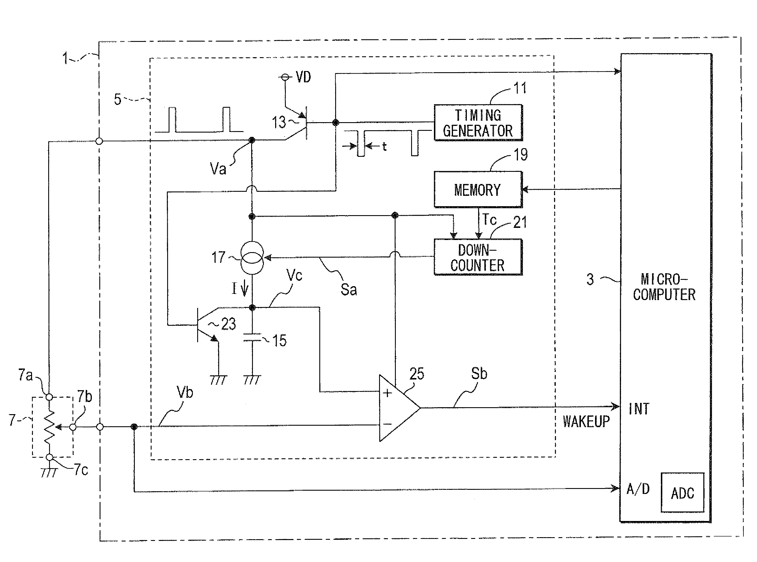
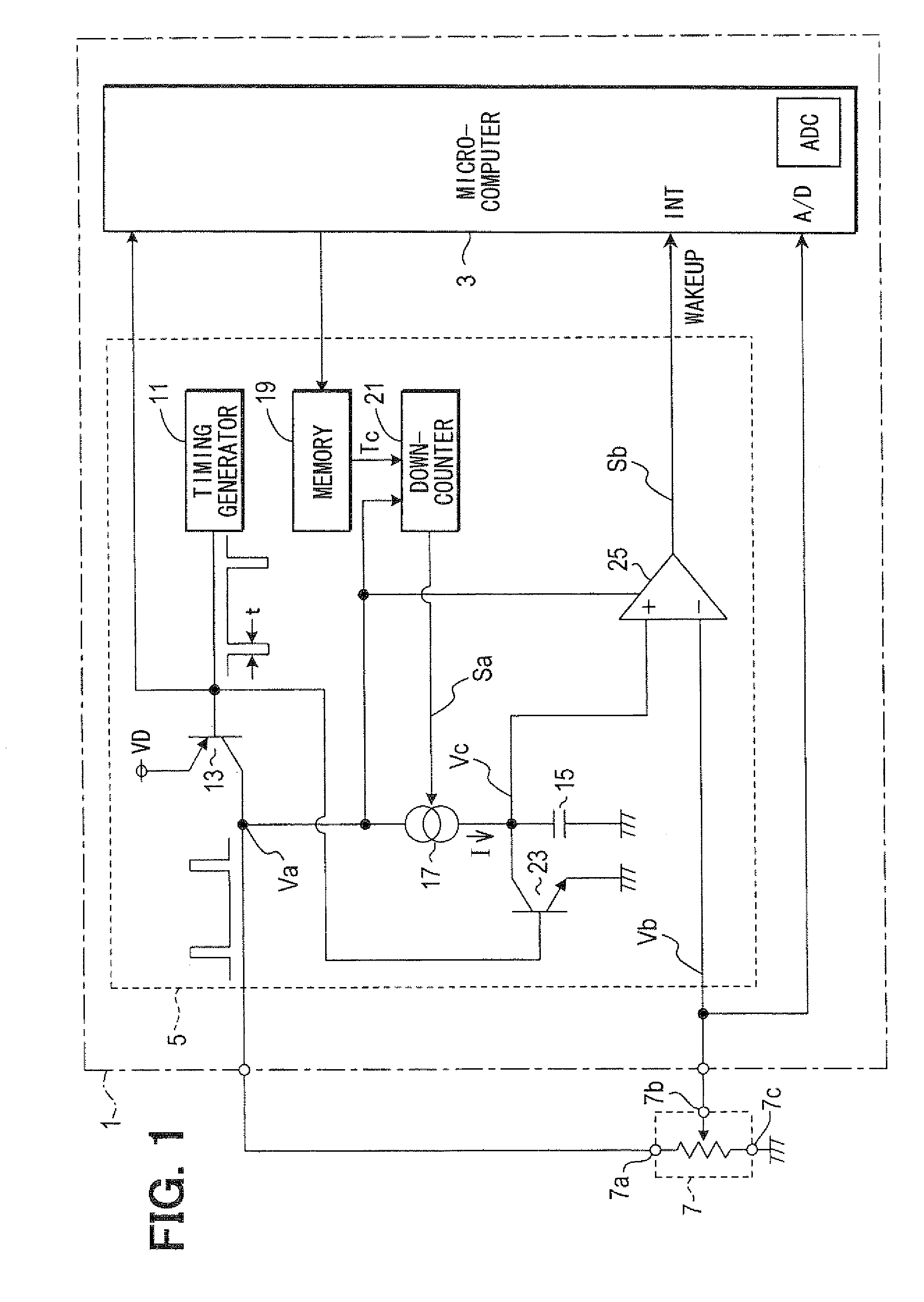
[0021]Referring first to FIG. 1, an electronic control unit (ECU) 1 is an in-vehicle ECU that operates with an in-vehicle battery as a power supply. The ECU 1 operates even when an ignition switch is off (in the off-state) during which the in-vehicle battery is not charged, and controls body system electric loads such as a door lock or a power window. This ECU 1 includes a microcomputer 3 that conducts various processing for controlling an object to be controlled, and a signal monitoring circuit 5. An A / D conversion input terminal A / D of the microcomputer 3 receives an analog signal Vb from a potentiometer 7 that functions as a brake pedal sensor which is disposed outside the ECU 1.

[0022]In the potentiometer 7, when it is assumed that a resistance between a signal output terminal 7b that outputs an analog signal Vb and a negative terminal 7c that is connected to a ground is R1, and a resistance between the signal output terminal 7b and a positive terminal 7a to which a supply voltag...

second embodiment

[0058]In the first embodiment, the potentiometer 7 is configured to decrease the voltage of the analog signal Vb by pressing down the brake pedal. On the other hand, in a second embodiment shown in FIG. 3, the potentiometer 7 is configured to increase the voltage of the analog signal Vb by pressing down the brake pedal.

[0059]That is, in the second embodiment, when the supply voltage VD is applied to the positive terminal 7a of the potentiometer 7, the analog signal Vb from the potentiometer 7 becomes a minimum value which is larger than 0V when the brake pedal is not pressed down, and becomes a voltage which is larger than the minimum value when the brake pedal is pressed down.

[0060]For this reason, an ECU 31 of the second embodiment is different from the ECU 1 of the first embodiment as follows.

[0061]First, the microcomputer 3 detects that the analog signal Vb from the potentiometer 7 when the supply voltage VD is applied to the microcomputer 3 is lower than the reference voltage V...


PUM


Abstract

An electronic control unit has a microcomputer and a signal monitoring circuit. When a brake pedal is pressed down and an analog signal from a brake pedal sensor is changed in a low power consumption operation mode of the microcomputer, the signal monitoring circuit operates cyclically, When the signal monitoring circuit starts the operation, a capacitor is charged with a constant current for only a charging time stored in a memory. When a comparator detects that the analog signal is lower than the charge voltage of the capacitor, a wakeup signal is output from the comparator to the microcomputer to cause the microcomputer to operate in the normal operation mode. The charging time is pre-stored in a memory of the microcomputer.

Description

CROSS REFERENCE TO RELATED APPLICATION[0001]This application is based on and incorporates herein by reference Japanese Patent Application No. 2007-237134 filed on Sep. 12, 2007.FIELD OF THE INVENTION[0002]The present invention relates to a technique which wakes up a microcomputer to shift it from a low power consumption operation mode to a normal operation mode.BACKGROUND OF THE INVENTION[0003]In an in-vehicle electronic control unit, a microcomputer disposed therein operates with an in-vehicle battery as a power supply.[0004]In the in-vehicle electronic control unit that is required to operate even when an ignition switch is off, that is, in the off-state during which the in-vehicle battery is not changed, particularly when the ignition switch is off, power consumption is required to be reduced as much as possible. For this reason, when given conditions including a condition where the ignition switch is off are satisfied, the operation mode is shifted to a low power consumption ope...

Claims


Application Information

Patent Timeline
IPC IPC(8): G06F1/32
CPCG06F1/3203H02J9/005G06F1/3209Y02B70/30Y04S20/20
Inventor KOBAYASHI, MIYUKI
Owner DENSO CORP
Why Eureka
Try Eureka