Door locking system having a planar striker plate

a technology of door locking and striker plate, which is applied in the direction of latching locks, non-mechanical controls, fastening means, etc., can solve the problems of manipulative movement of lock latches and significant difficulty in position, so as to improve fire, noise and heat insulation properties, and increase manipulation protection

Inactive Publication Date: 2009-03-19
ASSA ABLOY SICHERHEITSTECHN
View PDF11 Cites 16 Cited by
  • Summary
  • Abstract
  • Description
  • Claims
  • Application Information

AI Technical Summary

Benefits of technology

[0044]The opening procedure according to the present invention is distinguished by sequential execution of the following method steps: pivoting of the blocking piece of the door opener from the lock latch blocking position into the lock latch release position; extension of the lock latch blocking device into the lock latch receptacle space; sliding of the lock latch over the sliding bevel in the opening direction of the door and thus moving the lock latch from the “locked” position into the “unlocked” position; carrying along and / or lifting of the lock latch blocking device out of the lock latch receptacle space, without obstruction in particular in regard to the striker plate, in the area of the unblocking recess; sliding of the lock latch over the striker plate in the opening direction of the door; and extension of the latch blocking device and the lock latch after sliding over the striker plate into the “locked” position or into the “release position”. The essential feature of the method according to the invention for controlling an opening procedure is the carrying along of the lock latch blocking device by the lock latch in the area of the unblocking recess without obstruction and / or jamming. Only this step allows the lock latch sliding over the sliding bevel to carry along the lock latch blocking device out of the lock latch receptacle space and / or the unit made of lock latch receptacle and unblocking recess in the striker plate far enough that the lock latch blocking device is lifted over the outside surface of the striker plate. Only in this way is it possible to provide a contour completely enclosing these two recesses here, which finally results, for example, in improved fire, noise, and heat insulation properties and also very especially in increased manipulation protection.

Problems solved by technology

In the locked state of the door, manipulative moving of the lock latch from the “locked” position into the “unlocked” position is thus made significantly more difficult, because the lock latch is blocked by the lock latch blocking device, located in the “blocking position”.

Method used


Image

  • Door locking system having a planar striker plate
  • Door locking system having a planar striker plate
  • Door locking system having a planar striker plate

Examples


Embodiment Construction

[0063]In the embodiment described in the following, identical components are provided with identical reference numerals.

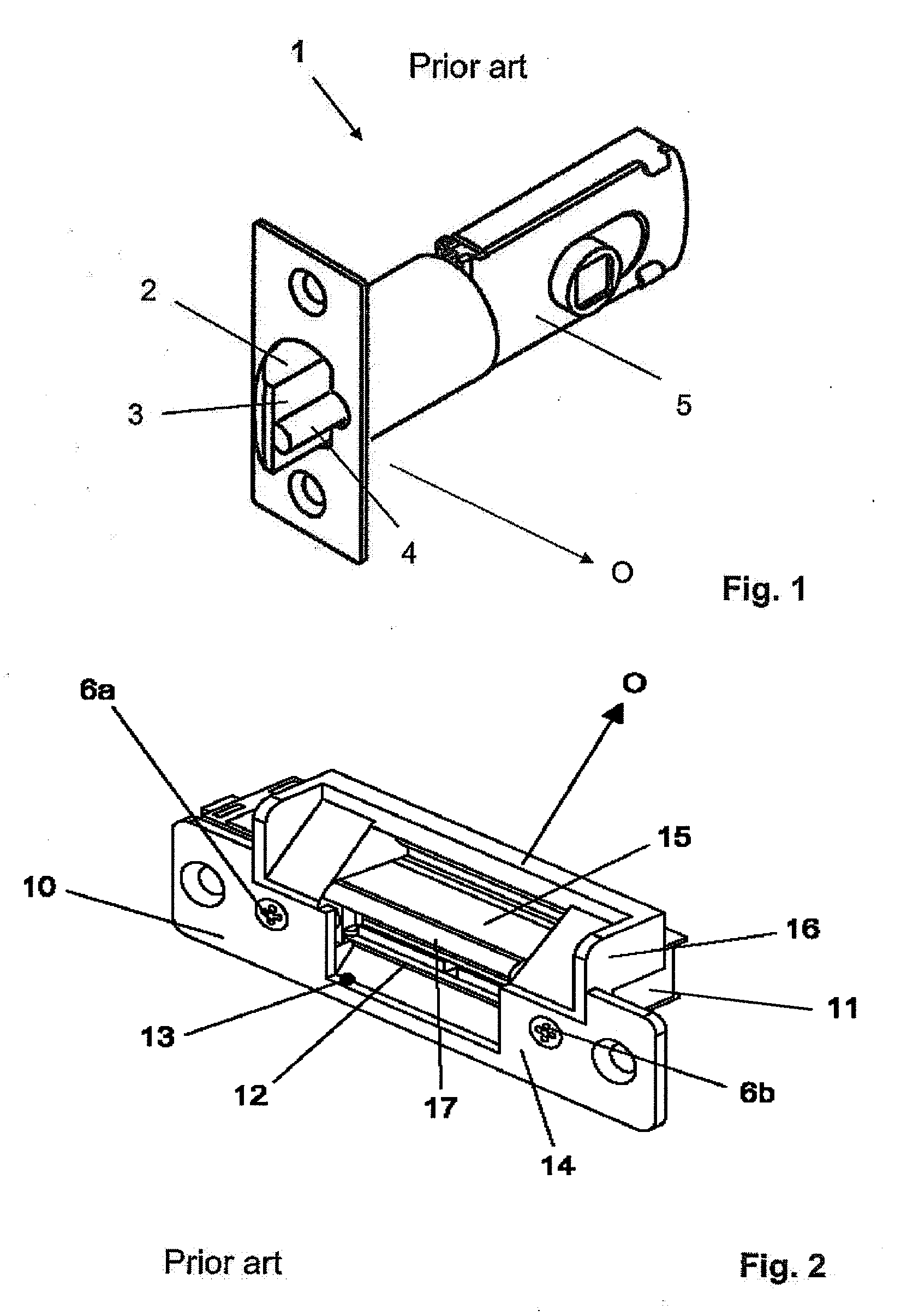
[0064]The door lock 1 from FIG. 1 is a cylinder lock known from the prior art. The door lock 1 is typically embedded in the cuff (not shown) of a door leaf (not shown) and has the lock latch 2 and the tracer pin 4, which presses against the planar back side 3 of the lock latch 2, projecting beyond the door cuff. Both the lock latch 2 and also the tracer pin 4 are spring-loaded and may thus be displaced from their extended position from FIG. 1 in the direction of the housing of the door lock 1 against a spring force.

[0065]To open a door (not shown) equipped with such a door lock 1, the door lock 1 comprises an actuating mechanism, identified as a whole by 5. The actuating mechanism is implemented in such a way that the projecting lock latch 2 and the projecting tracer pin 4 may be moved back against the spring force in the direction of the door lock 1 by applying a ...


PUM


Abstract

A door locking system has a lock latch which is movable between a locked position projecting beyond a door lock cuff and a unlocked position retracted in the direction of the door lock cuff, and has a lock latch blocking device, movable between a blocking position and a release position, which fixes the lock latch in the locked position in the blocking position retracted toward the door lock, and releases the lock latch in the release position, which is extended in relation to the blocking position, in such a way that the lock latch is displaceable between the locked position and the unlocked position. The door locking system has a driver control mechanism.

Description

PRIORITY[0001]The present invention claims priority of German Patent Application No. 102007014324.0 filed Mar. 26, 2007, the contents of which are incorporated herein in its entirety.BACKGROUND OF THE INVENTION[0002]The present invention relates to a door locking system, a striker plate for use in a door locking system, and a method for controlling a door locking system according to the independent claims.[0003]A door locking system according to the species comprises a door lock situated in a door, an essentially planar striker plate, and a door opener.[0004]The door lock has a lock latch, which is movable between a “locked” position projecting beyond the door lock cuff and a “unlocked” position retracted in the direction of the door lock cuff. Furthermore, a lock latch blocking device is provided on the door lock, which is movable between a “blocking” position and a “release” position. The lock latch blocking device is implemented for blocking the lock latch located in the “locked”...

Claims


Application Information

Patent Timeline
Patent Type & Authority Applications(United States)
IPC IPC(8): E05B15/02
CPCE05B15/0205E05B55/005E05B47/0047Y10T292/699Y10T292/696
Inventor HOLZER, MICHAEL
Owner ASSA ABLOY SICHERHEITSTECHN
Why Eureka
Try Eureka