
Eureka
For R&D, Eureka makes reading and utilizing patents & technical documents easy.
Eureka AIR
Designed for self-driven R&D workflows. Generate viable solutions, solve complex R&D challenges, empower your innovation with AI.

Eureka Materials
Designed for material experts only. Revolutionize your material R&D, from search, analyze, to developing new materials.

TechResearch
Generate reliable direction feasibility study reports for your R&D in just a few steps.

TechSeek
Discover and master advanced knowledge NOW. Basics, ideas, possibilities, all at once.

TechMind
As an expert in R&D Theories, TechMind can generates customized viable solutions instantly.

TechRisk
Analyze your overall solution with one click, know your potential R&D risks in advance.

TechMonitor
Get weekly tech updates, stay abreast of the latest tech innovations and key insights.
Axial gap-type electric motor
- Summary
- Abstract
- Description
- Claims
- Application Information
AI Technical Summary
Benefits of technology
Problems solved by technology
Method used
Image

Examples
first exemplary embodiment
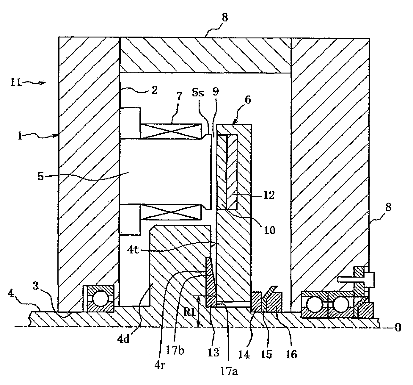
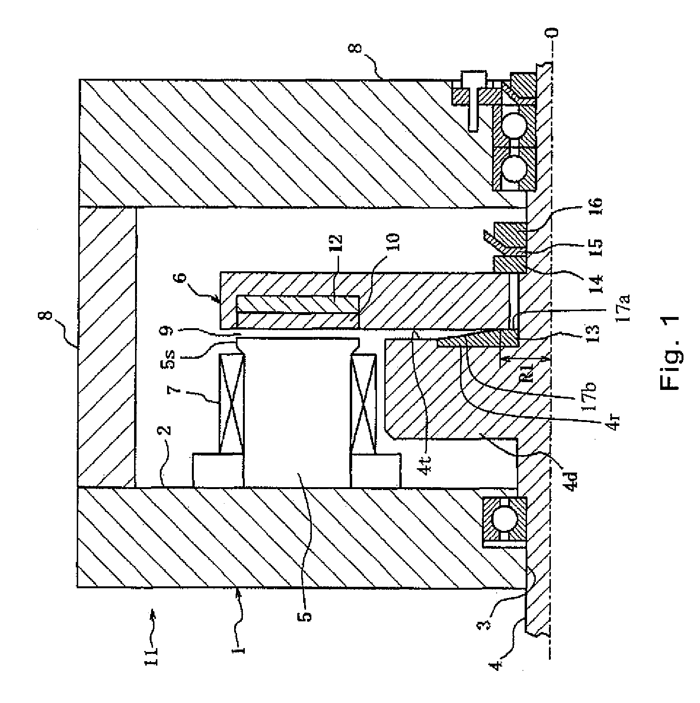
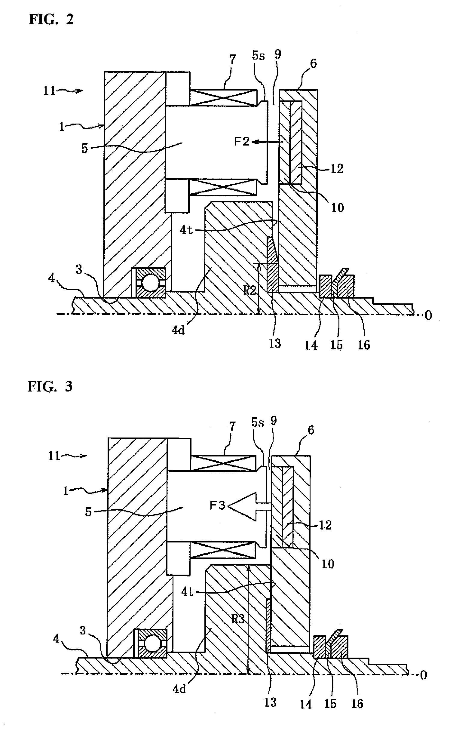
[0035]FIGS. 1 to 3 are cross-sectional views schematically showing a structure of an axial gap-type electrical motor in accordance with a first exemplary embodiment of the present disclosure.
[0036]A stator 1 of an axial gap-type electrical motor 11 comprises a stator core 2, a stator iron core 5 and an armature winding 7.
[0037]The stator core 2 formed of electromagnetic materials has a circular ring shape and an outer periphery of the stator core 2 is supported by and fixed to a motor case 8. Further, a center hole 3 is formed in a center portion of the stator core 2 to receive an output shaft 4. The output shaft 4 is rotatably supported at a bearing installed in the center hole 3. The stator core 2, includes several stator iron cores 5 which are disposed at an equal distance from each other and arranged to correspond to the circumference of the stator core 2. Each stator iron core 5 may be formed by stacking steel plates, and protrudes from the stator core 2 in the axial direction ...
second exemplary embodiment
[0054]FIGS. 5 to 7 are cross-sectional section views schematically showing a structure of an axial gap-type electrical motor 21 in accordance with a second exemplary embodiment of the present disclosure. FIG. 5 shows a state when the radius of the contact surface is small (R1). FIG. 6 shows a state when the radius of the contact surface is greater than that shown in FIG. 5 (R2). FIG. 7 shows a state when the radius of the contact surface is greater than that shown in FIG. 6 (R4). Because the basic constitution of the second exemplary embodiment is similar to that of the first exemplary embodiment, similar elements are denoted by the same reference numerals and explanations thereof are omitted herein.
[0055]An axial gap-type electrical motor 21 in accordance with the second exemplary embodiment has a ring-shaped stopper 23 through which the output shaft 4 passes. Although a material of the stopper 23 may be the same as the stopper 13 of the first exemplary embodiment, the contact surf...
third exemplary embodiment
[0064]FIGS. 9 and 10 are cross-sectional section views schematically illustrating a structure of an axial gap-type electrical motor 31 in accordance with a third exemplary embodiment of the present disclosure. FIG. 9 shows a state when the radius of the contact surface is relatively small (R1). FIG. 10 shows a state when the radius of the contact surface is relatively large (i.e., greater than FIG. 9) (R3). Because the basic constitution of the second exemplary embodiment is similar to that of the first exemplary embodiment, similar elements are denoted by the same reference numerals and explanations thereof are omitted herein.
[0065]An axial gap-type electrical motor 31 in accordance with the third exemplary embodiment comprises a stopper 33 through which the output shaft 4 is passes. Although a material of the stopper 33 may be the same as stopper 13 of the first exemplary embodiment, stopper 33 is shown such that its contact surface is neither a linear taper or an arcuate taper. R...
PUM
 Abstract
Description
Claims
Application Information
 - R&D Engineer
- R&D Manager
- IP Professional
- Industry Leading Data Capabilities
- Powerful AI technology
- Patent DNA Extraction
Browse by: Latest US Patents, China's latest patents, Technical Efficacy Thesaurus, Application Domain, Technology Topic, Popular Technical Reports.
© 2024 PatSnap. All rights reserved.Legal|Privacy policy|Modern Slavery Act Transparency Statement|Sitemap|About US| Contact US: help@patsnap.com