Ceramic lamp holder

a ceramic lamp and lamp holder technology, applied in the field of lamps, can solve the problems of poor contact the friction between the outer thread and the inner thread is so large, and the above-mentioned conventional lamp holder still has some problems, so as to increase the life of the bulb, and increase the temperature

Inactive Publication Date: 2009-03-19
RICHARD LEE
View PDF6 Cites 0 Cited by
  • Summary
  • Abstract
  • Description
  • Claims
  • Application Information

AI Technical Summary

Benefits of technology

[0009]The present invention is to provide a ceramic lamp holder, in which the cylinder is made of a ceramic material that can withstand a higher temperature and dissipate the heat of the filament or bulb quickly, thereby increasing the lifetime of the bulb.
[0010]The present invention is to provide a ceramic lamp holder, which is simple in structure and can be assembled easily. Furthermore, the present invention can reduce the material cost and the manufacture cost substantially.

Problems solved by technology

However, in practice, the above-mentioned conventional lamp holder still has some problems as follows.
Since the outer thread of the outer connecting piece is connected to the inner thread (not shown) of the lamp socket via full circles of rotation, the wear caused by the friction between the outer thread and the inner thread is so large that the contact therebetween may become poor after several times of rotation.
Furthermore, there is a number of constituent components, so that the manufacture cost and material cost of those components are increased.
Also, a large amount of labor hours should be spent to assemble the conventional lamp holder.
On the other hand, the inner connecting piece and the outer connecting piece cannot withstand high temperature very well.
Therefore, after operating continuously for a long time, the inner connecting piece and the outer connecting piece may be overheated to suffer damage, which lowers the lifetime thereof.
Therefore, it is an important issue to overcome the above-mentioned problems in prior art.

Method used


Image

  • Ceramic lamp holder
  • Ceramic lamp holder
  • Ceramic lamp holder

Examples


Embodiment Construction

[0016]The detailed description and technical contents of the present invention will be explained with reference to the accompanying drawings. However, the drawings are illustrative only, but not used to limit the present invention.

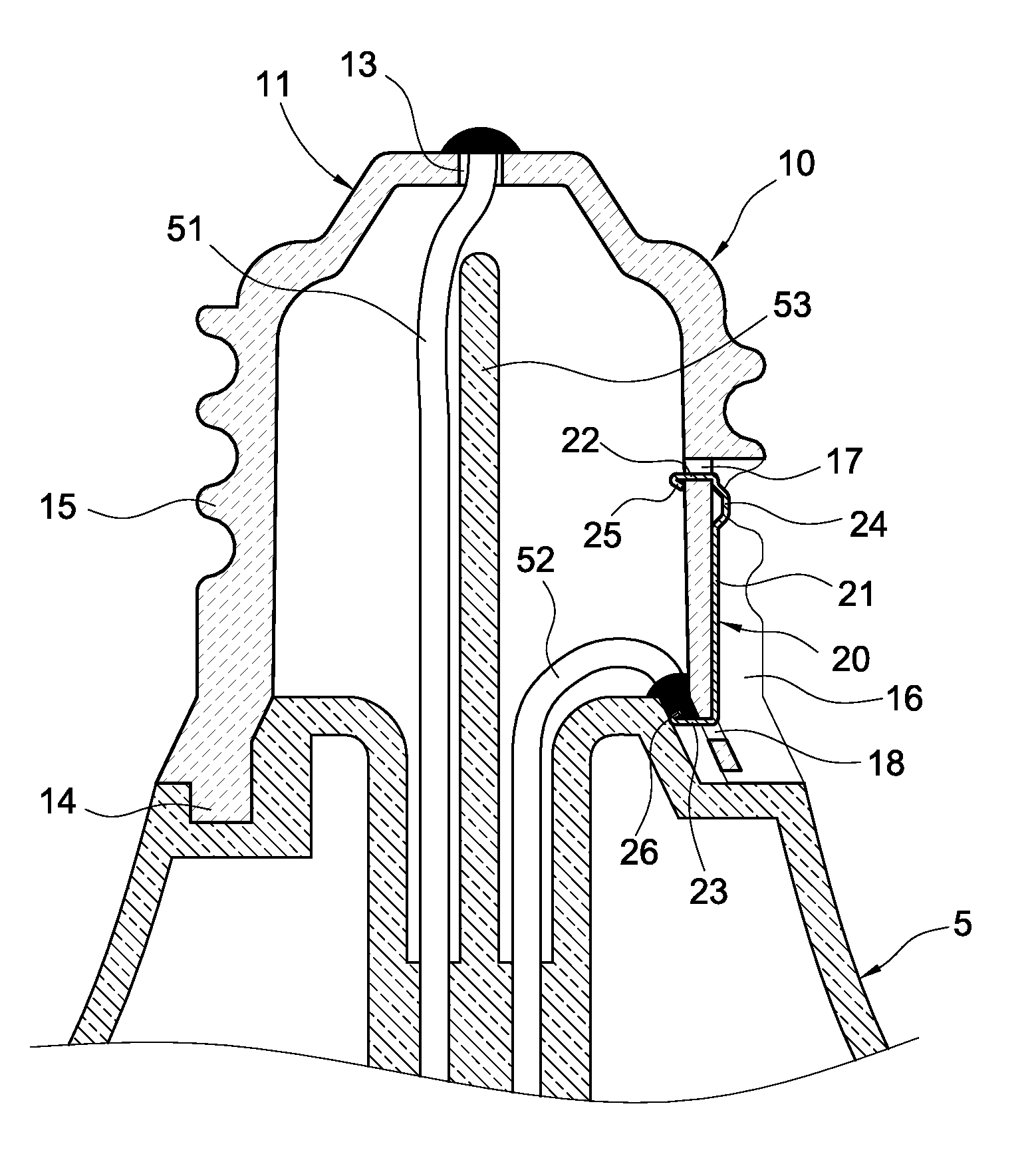
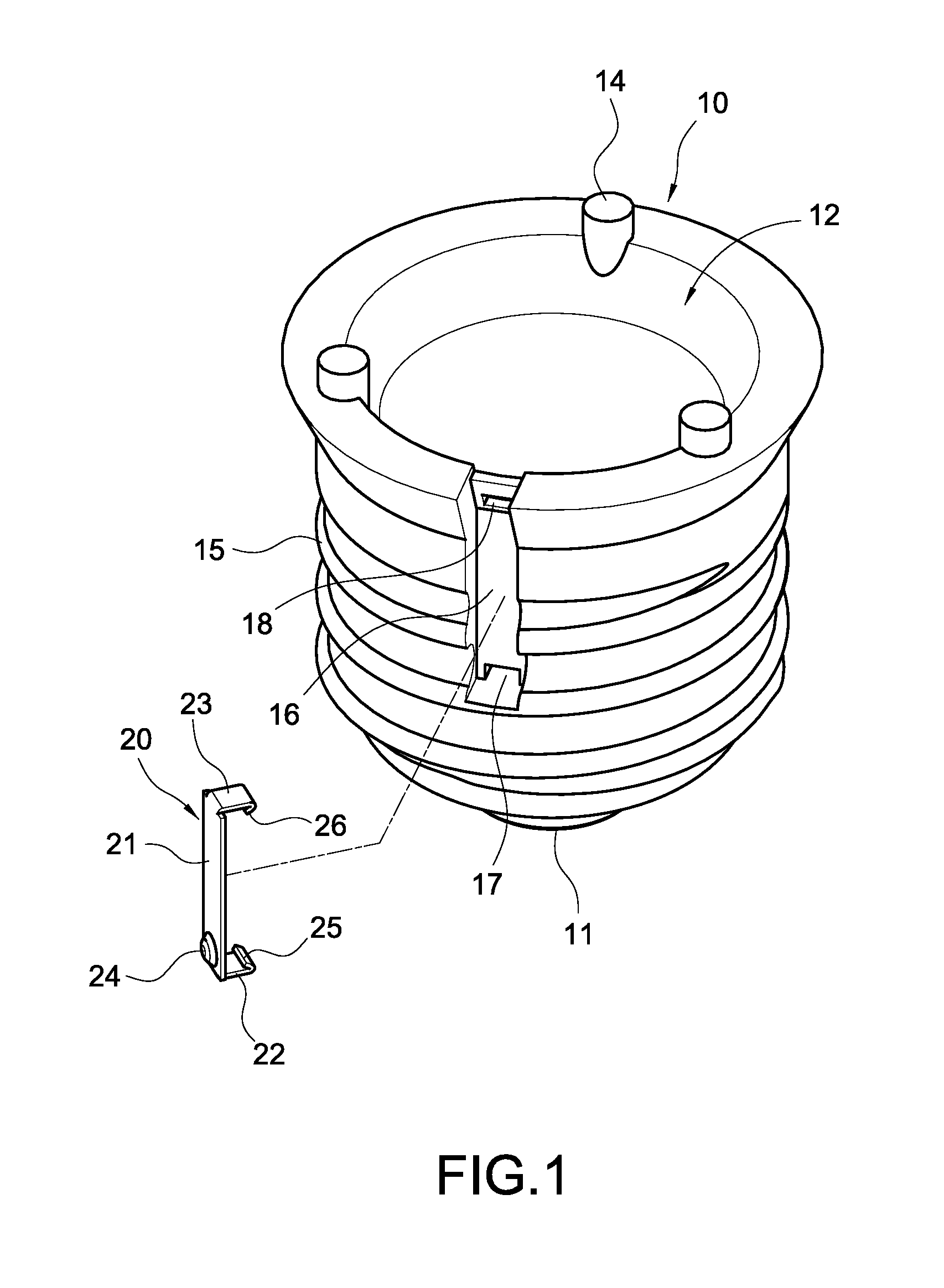
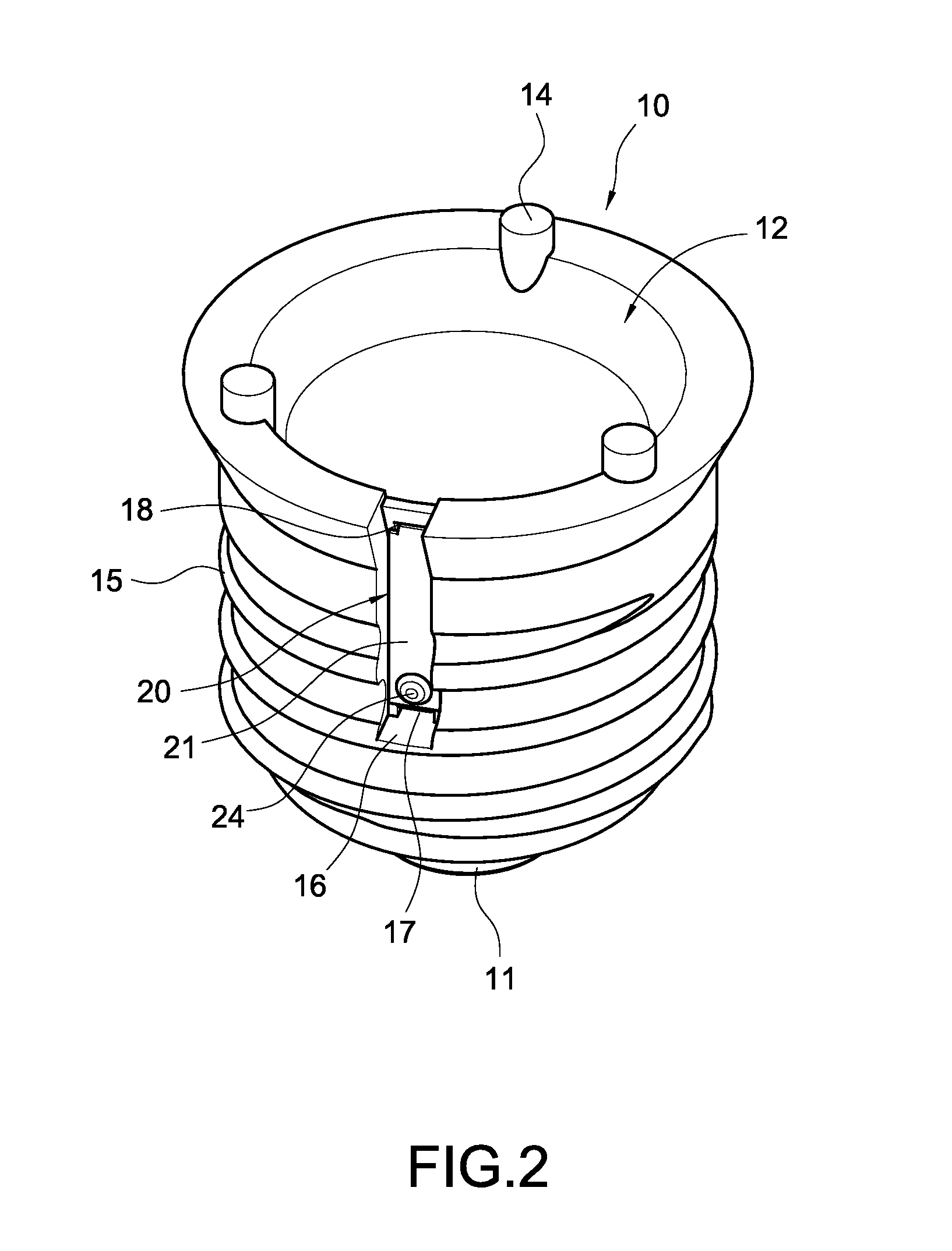
[0017]Please refer to FIG. 1 to 3. FIGS. 1, 2 and 3 are an exploded perspective view, an assembled view and an assembled cross-sectional view of the present invention respectively. The present invention provides a ceramic lamp holder, which includes a cylinder 10 and a conductive terminal 20.

[0018]The cylinder 10 is made of a ceramic material and is formed into a circular shape. Both sides of the cylinder 10 are formed into a conical closed end 11 and an open end 12. The center of the closed end 11 is provided with a through hole 13 (FIG. 3). The periphery of the open end 12 of the cylinder 10 is formed with a plurality of outwardly-extending insertion posts 14. The outer periphery of the cylinder 10 is formed with an outer thread 15 and a trough 16 recess...


PUM


Abstract

A ceramic lamp holder for connecting a bulb and communicating with a filament of the bulb includes a cylinder and a conductive terminal. The cylinder is made of ceramic material with its one side formed into a closed end. The closed end is provided with a through hole for allowing one end of the filament to pass through. The outer surface of the cylinder is formed with an outer thread and a trough recessed into the surface of the outer thread. The conductive terminal is fixedly received in the trough to be partially exposed to the surface of the outer thread. One end of the conductive terminal is connected to the other end of the filament. Via the above arrangement, the wear caused by the friction between the conductive terminal and the lamp socket can be reduced, and the contact effect and the life time of the lamp holder can be increased.

Description

BACKGROUND OF THE INVENTION[0001]1. Field of the Invention[0002]The present invention relates to a lamp, and in particular to a lamp holder for connecting a bulb.[0003]2. Description of Prior Art[0004]Taiwan Patent Publication No. M258232 discloses a conventional lamp holder, which includes an outer connecting piece, an inner connecting piece and an insulating ring. The outer connecting piece is made of a metallic material such as copper and partially covers the outer surface of the insulating ring. The outer peripheral surface of the outer connecting piece is formed with an outer thread. The inner connecting piece and the outer connecting piece are separated from each other and are connected to the center of the top of the insulating ring. With the inner connecting piece and the outer connecting piece being welded with an inner filament and an outer filament of the bulb respectively, the assembly of the bulb and the lamp holder can be achieved.[0005]However, in practice, the above-...

Claims


Application Information

Patent Timeline
Patent Type & Authority Applications(United States)
IPC IPC(8): H01J5/48
CPCH01J5/56H01K1/46H01J5/62
Inventor LEE, RICHARD
Owner RICHARD LEE
Why Eureka
Try Eureka