Image forming apparatus and method of controlling the same

a technology control method, which is applied in the direction of electrographic process apparatus, instruments, optics, etc., can solve the problems of power consumption increase, power supply voltage fluctuation, and increased size of image forming apparatus

Active Publication Date: 2009-03-19
RICOH KK
View PDF2 Cites 39 Cited by
  • Summary
  • Abstract
  • Description
  • Claims
  • Application Information

AI Technical Summary

Benefits of technology

[0010]It is an object of the present invention to at least

Problems solved by technology

To realize the high image formation speed, the image forming apparatuses are increased in size and power consumption thereof also increases.
When the heaters of the fixing device are turned on and off, fluctuation in a power supply voltage tends to be caused by current consumption and the like of the heaters.
This may cause flicker, harmonic distortion, terminal noise, and the like in other electronic apparatuses that use the sam

Method used


Image

  • Image forming apparatus and method of controlling the same
  • Image forming apparatus and method of controlling the same
  • Image forming apparatus and method of controlling the same

Examples


Embodiment Construction

[0042]Exemplary embodiments of the present invention are explained in detail below with reference to the accompanying drawings.

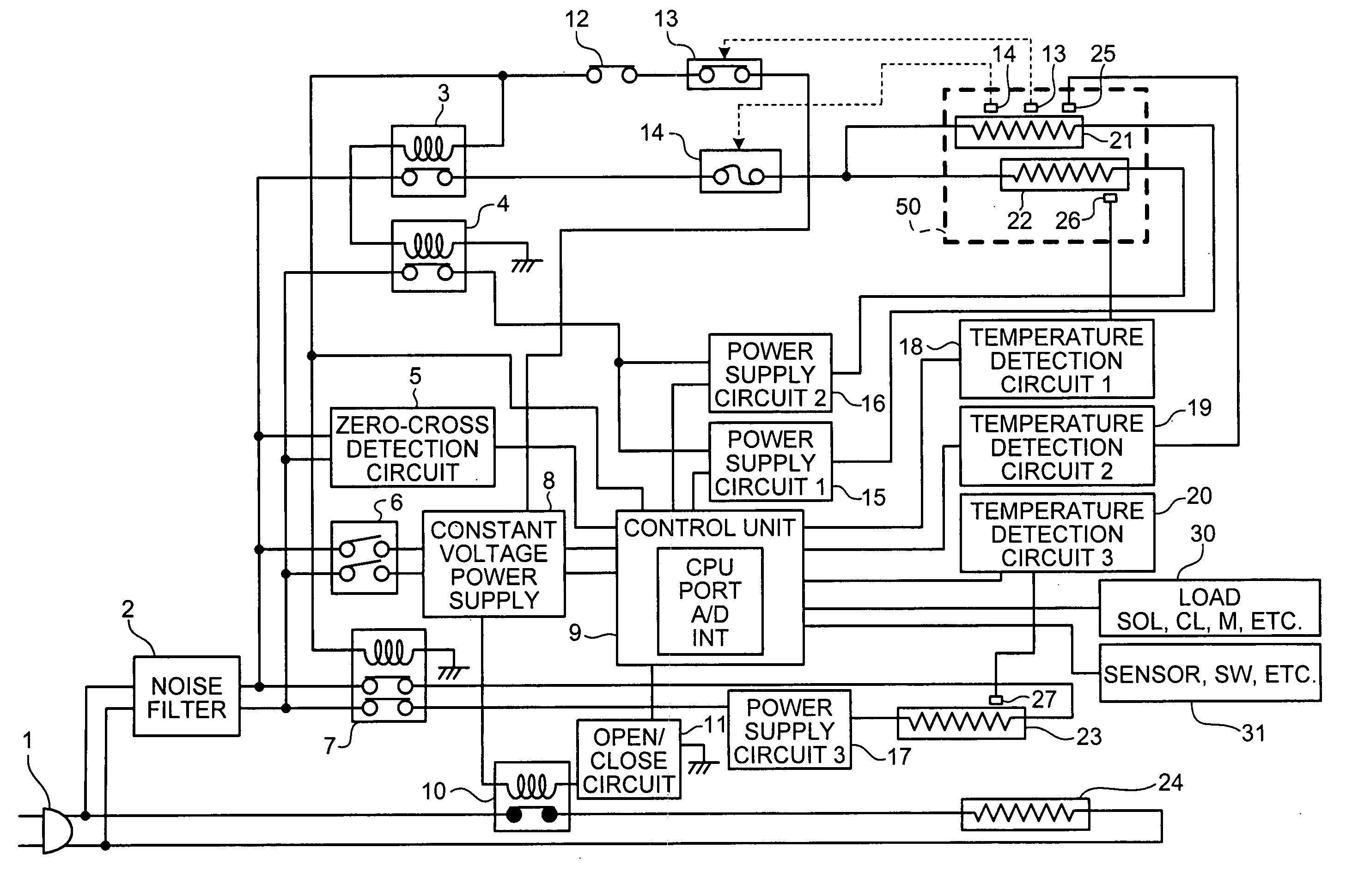
[0043]FIG. 3 is a diagram of an AC power control circuit of an image forming apparatus according to an embodiment of the present invention.

[0044]In the AC power control circuit shown in FIG. 3, a pair of power supply lines connected to an AC plug 1 put into a socket of an AC 100 volts commercial power supply are connected to normally-open contacts of a relay 7, a relay 3, and a relay 4, a main power switch 6, and the zero-cross detection circuit 5 through a noise filter 2. On the other hand, the power supply line is also connected to a normally-closed contact of a relay 10, a dehumidifying heater 24, and a series circuit.

[0045]An open / close contact of the relay 3 is connected to one terminal of a heating center heater 21 as first heating means and one terminal of a heating end heater 22 as second heating means of a fixing device via a thermostat 14.

[0046]On ...


PUM


Abstract

A control unit controls supply of power to a plurality of heating units at predetermined control period T1 that is set by a first unit. A second unit sets power supply time t1 for a first heating unit having largest power consumption within the control period T1 and power supply time t2 for a second heating unit having second largest power consumption. A third unit controls to supply the power to the first heating unit for the power supply time t1 from beginning of the control period T1 and to supply the power to the second heating unit from a point obtained by subtracting the power supply time t2 from end of the control period T1 to the end of the control period T1.

Description

CROSS-REFERENCE TO RELATED APPLICATIONS[0001]The present application claims priority to and incorporates by reference the entire contents of Japanese priority document 2007-239457 filed in Japan on Sep. 14, 2007.BACKGROUND OF THE INVENTION[0002]1. Field of the Invention[0003]The present invention relates to an image forming apparatus such as a copying machine, a printer, a facsimile apparatus, and a digital multifunction product of an electrophotographic system, and more particularly, to an image forming apparatus including a plurality of heating units in a fixing device that fixes a toner image on a recording medium and a method of controlling the image forming apparatus.[0004]2. Description of the Related Art[0005]In recent years, there is an increasing demand for high image formation speed in image forming apparatuses. To realize the high image formation speed, the image forming apparatuses are increased in size and power consumption thereof also increases.[0006]In particular, la...

Claims


Application Information

Patent Timeline
IPC IPC(8): G03G15/20G03G15/00
CPCG03G15/5004G03G15/2039G03G2215/2006G03G15/80
Inventor SANO, TAKESHIOKADA, NORIKAZU
Owner RICOH KK
Why Eureka
Try Eureka