Test socket

Active Publication Date: 2009-03-19
SHARP KK
View PDF10 Cites 3 Cited by
  • Summary
  • Abstract
  • Description
  • Claims
  • Application Information

AI Technical Summary

Benefits of technology

[0018]Since the test socket according to the above-described features includes the urging means for urging the first locating means in the second direction and the position setting means for setting the upper limit of the movement in the second direction of the first locating means caused by the urging means, it becomes possible to control the position in the second direction of the first locating means as appropriate relative to the solid-state image pickup device in the housed state. With this structure, in the case of, e.g., performing a test on a solid-state image pickup device mounted with a circuit board, the test socket according to the above-described features can set the position where the first locating means contacts the solid-state image pickup device to a position outside the circuit board mounting portion. Accordingly, the test socket according to the above-described features can be used for solid-state image pickup devices of different shapes more flexibly, hence allowing a solid-state image pickup device to be housed and fixed therein regardless of present or absence of a built-in circuit board.
[0019]Also, since the test socket according to the above-described features includes the first locating means for locating the solid-state image pickup device in the direction (the first direction) parallel to the ceiling plane of the solid-state image pickup device in the housed state, the locating in the first direction can be performed accurately. With this structure,

Problems solved by technology

In a case, however, where, e.g., a test is performed using a conventional test socket on a solid-state image pickup device mounted with a circuit board, and the circuit board is mounted at such a position that locating means of the test socket contacts th

Method used


Image

  • Test socket
  • Test socket
  • Test socket

Examples


Example

[0030]Embodiments of a test socket according to the present invention are described below with reference to the drawings.

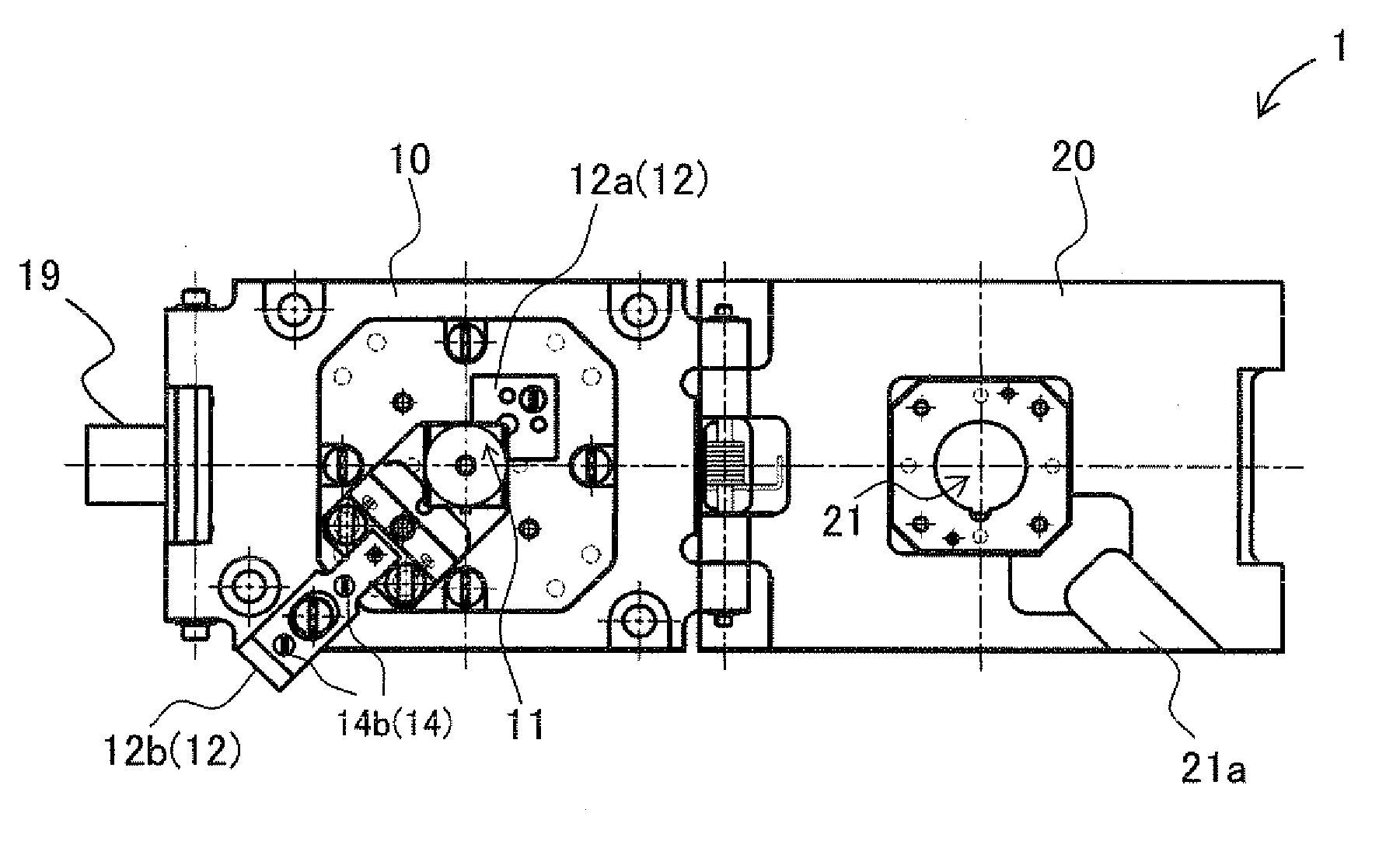
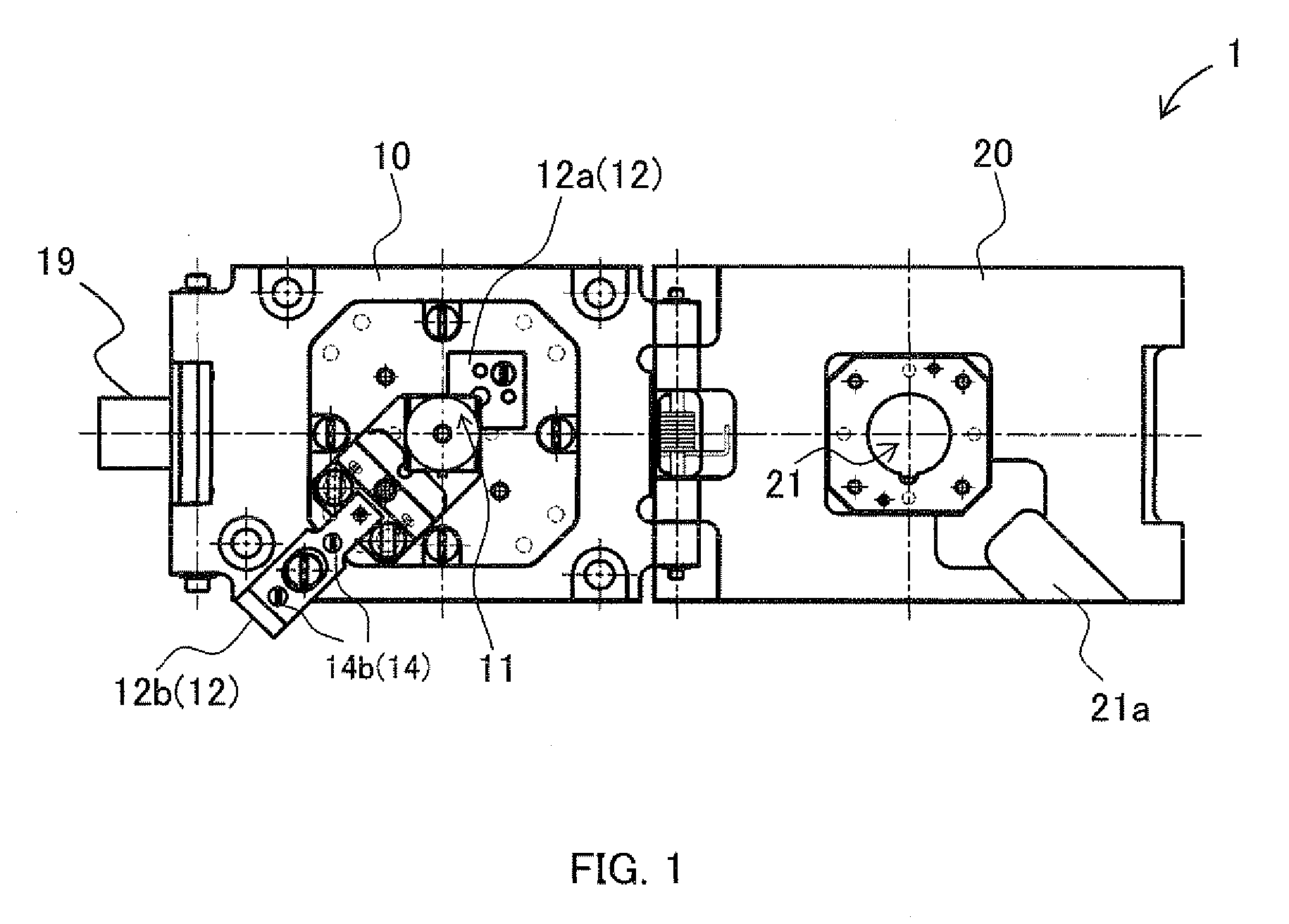
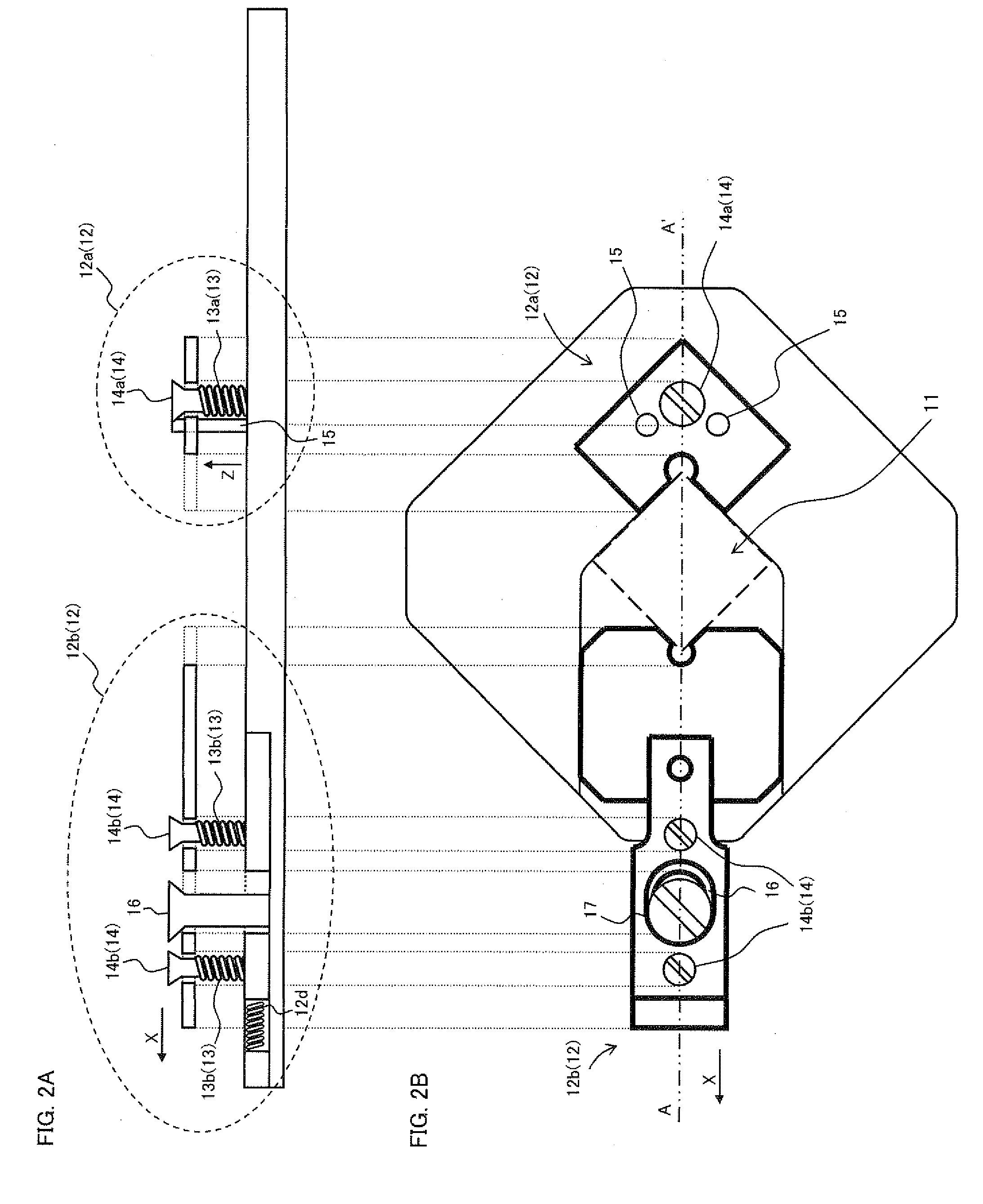
[0031]A structure of a test socket according to the present invention is described with reference to FIGS. 1 to 6. FIG. 1 shows an exemplary schematic configuration of an opened test socket 1 according to the present invention. FIGS. 2A and 2B show exemplary schematic configurations of main portions of a base 10 to be described later of the test socket 1 shown in FIG. 1, where FIG. 2A is a cross-sectional view taken along line A-A′ in FIG. 2B, and FIG. 2B is a top view of the base 10. It should be noted that the present embodiment is described on the assumption that the tested device to be housed in the test socket is a solid-state image pickup device that includes a circuit board in a lower portion of its main body and an image pickup portion on its ceiling plane.

[0032]As shown in FIG. 1, the test socket 1 includes the base 10 and a cover 20 that have an approxim...


PUM


Abstract

Provided is a test socket capable of being used more flexibly for solid-state image pickup devices of different shapes and of performing locating of the solid-state image pickup devices more precisely. The test socket houses a tested device which is a solid-state image pickup device while a test is being performed. The test socket comprises: first locating means for locating the tested device in an X direction parallel to a ceiling plane of the tested device in a housed state; urging means for urging the first locating means in a Z direction perpendicular to the ceiling plane of the tested device in the housed state; and position setting means for setting an upper limit of movement in the Z direction of the first locating means caused by the urging means to set a position in the Z direction of the first locating means relative to the tested device.

Description

CROSS REFERENCE TO RELATED APPLICATION[0001]This Nonprovlsional application claims priority under 35 U.S.C. §119(a) on Patent Application No. 2007-238827 filed in Japan on Sep. 14, 2007, the entire contents of which are hereby incorporated by reference.BACKGROUND OF THE INVENTION[0002]1. Field of the Invention[0003]The present invention relates to a test socket including locating means for locating a solid-state image pickup device fitted therein.[0004]The present invention relates to a socket configured to locate a solid-state image pickup device inserted therein so as to enable optical centering at all times, and hence being adaptable to solid-state image pickup devices of different sizes.[0005]2. Description of the Related Art[0006]Recently, with the remarkable advancement in performance of image pickup instruments using solid-state image pickup devices, such as cellular phones with a camera function and digital still cameras, the solid-state image pickup devices have also become...

Claims


Application Information

Patent Timeline
IPC IPC(8): H01R13/64G01R31/26H01L27/14H01R33/76H04N5/335H04N17/00
CPCH01R13/627H01R12/88H01R2201/20
Inventor SAITOH, HITOSHITSUJI, MAKOTO
Owner SHARP KK
Why Eureka
Try Eureka