
Method and system for calibrating a power amplifier

a power amplifier and power amplifier technology, applied in the field of wireless communication, can solve the problems of increasing the complexity of designing the communication system, increasing the cost of equipment, etc. existing frequency bands are becoming increasingly congested, and the available frequency band is becoming increasingly scar

Active Publication Date: 2009-03-19
AVAGO TECH INT SALES PTE LTD
View PDF3 Cites 61 Cited by
  • Summary
  • Abstract
  • Description
  • Claims
  • Application Information

AI Technical Summary

Benefits of technology

[0005]A system and / or method is provided for calibrating a power amplifier, substantially as shown in and / or described in connection with at least one of the figures, as set forth more completely in the claims.

Problems solved by technology

With the rapidly increasing dependence on electronic communications and the accompanying efforts to make these communications faster and cheaper, the complexity of designing communications systems is also increasing.
For example, available frequency bands, which are regulated by organizations such as the FCC in the USA, are becoming increasingly scarce.
Moreover, existing frequency bands are becoming increasingly congested due to the plethora of users and devices in existence.
Accordingly, designing devices that can reliably operate in such noisy frequency bands is becoming increasingly difficult and costly.
Another example of the complexities facing communication system designers is that making communication devices faster and cheaper often means integrating more functionality into smaller chips and systems.
In this regard, although increased integration may lead to lower product cost, it may also greatly increase the amount of effort required for designing such systems.
For example, due to variations in fabrication processes integrated systems can exhibit significant differences in performance between lots and even between wafers.

Method used


Image

  • Method and system for calibrating a power amplifier
  • Method and system for calibrating a power amplifier
  • Method and system for calibrating a power amplifier

Examples


Embodiment Construction

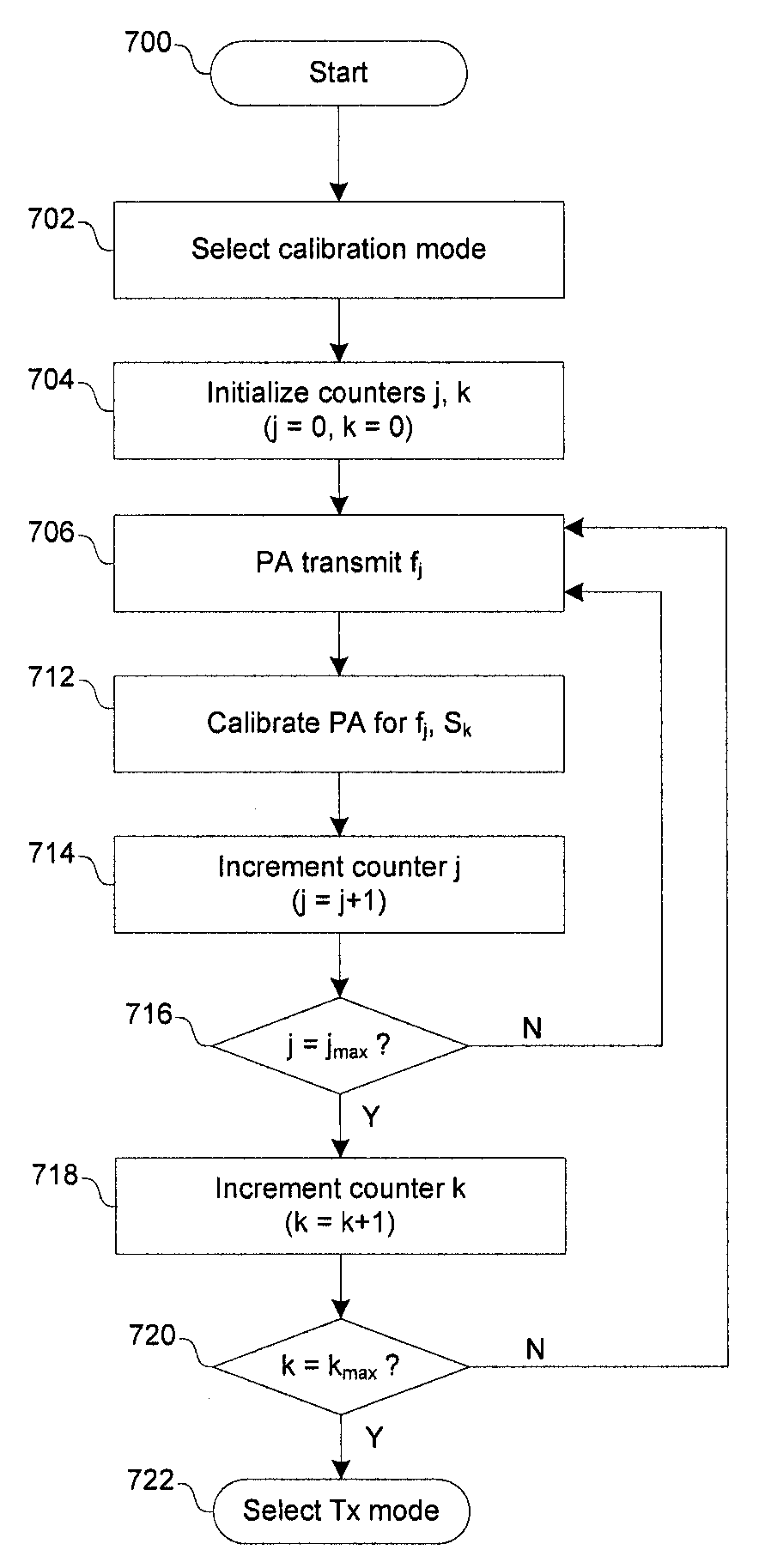
[0015]Certain embodiments of the invention may be found in a method and system for calibrating a power amplifier. In this regard, one or more reference signals may be generated and may be utilized to characterize a signal strength indicator. Additionally, measurements of power output by a power amplifier by the signal strength indicator (SSI) may be corrected based on the characterization of the SSI. Accordingly, the power amplifier may be adjusted based on the corrected measurements. The reference signals utilized to characterize the SSI may be limited to a determined range. In this regard, signal strength of the reference signals, as measured by the SSI, may be compared to the expected signal strength in order to characterize the SSI. The SSI may be characterized over a range of frequencies and / or signal strengths. Similarly the power amplifier may be adjusted over a range of frequencies and / or signal strengths.

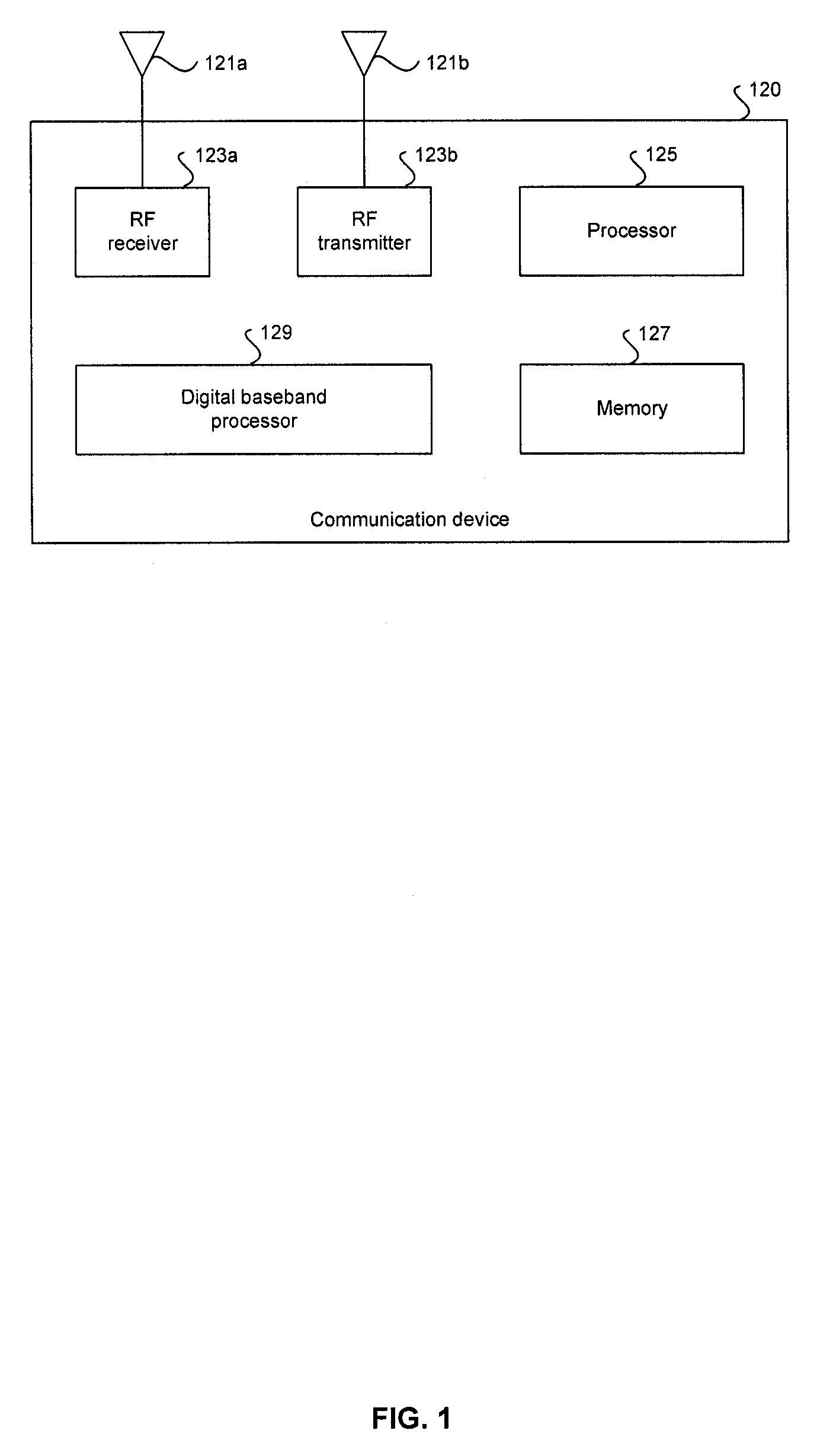
[0016]FIG. 1 is a block diagram illustrating an exemplary RF communica...


PUM


Abstract

Aspects of a method and system for calibrating a power amplifier are provided. In this regard, one or more reference signals may be generated and may be utilized to characterize a signal strength indicator (SSI). Additionally, measurements of power output by a power amplifier by the SSI may be corrected based on the characterization of the SSI. Accordingly, the power amplifier may be adjusted based on the corrected measurements. The reference signals utilized to characterize the SSI may be limited to a determined range. In this regard, signal strength of the reference signals, as measured by the SSI, may be compared to the expected signal strength in order to characterize the SSI. The SSI may be characterized over a range of frequencies and / or signal strengths. Similarly the power amplifier may be adjusted over a range of frequencies and / or signal strengths.

Description

CROSS-REFERENCE TO RELATED APPLICATIONS / INCORPORATION BY REFERENCE[0001]Not ApplicableFIELD OF THE INVENTION[0002]Certain embodiments of the invention relate to wireless communication. More specifically, certain embodiments of the invention relate to a method and system for calibrating a power amplifier.BACKGROUND OF THE INVENTION[0003]With the rapidly increasing dependence on electronic communications and the accompanying efforts to make these communications faster and cheaper, the complexity of designing communications systems is also increasing. For example, available frequency bands, which are regulated by organizations such as the FCC in the USA, are becoming increasingly scarce. Moreover, existing frequency bands are becoming increasingly congested due to the plethora of users and devices in existence. Accordingly, designing devices that can reliably operate in such noisy frequency bands is becoming increasingly difficult and costly. Another example of the complexities facing ...

Claims


Application Information

Patent Timeline
Patent Type & Authority Applications(United States)
IPC IPC(8): H04B17/00
CPCH04B17/001H04B17/21H04B17/13H04B17/0062
Inventor ROFOUGARAN, AHMADREZA
Owner AVAGO TECH INT SALES PTE LTD
Features
  • Generate Ideas
  • Intellectual Property
  • Life Sciences
  • Materials
  • Tech Scout
  • Unparalleled Data Quality
  • Higher Quality Content
  • 60% Fewer Hallucinations
Learn More