
System for the automatic movement of material

a technology of automatic movement and material, applied in the direction of distance measurement, navigation instruments, instruments, etc., can solve the problem of preventing the free movement of equipmen

Inactive Publication Date: 2009-03-19
LIEBHERR WERK BISCHOFSHOFEN GES
View PDF10 Cites 70 Cited by
  • Summary
  • Abstract
  • Description
  • Claims
  • Application Information

AI Technical Summary

Benefits of technology

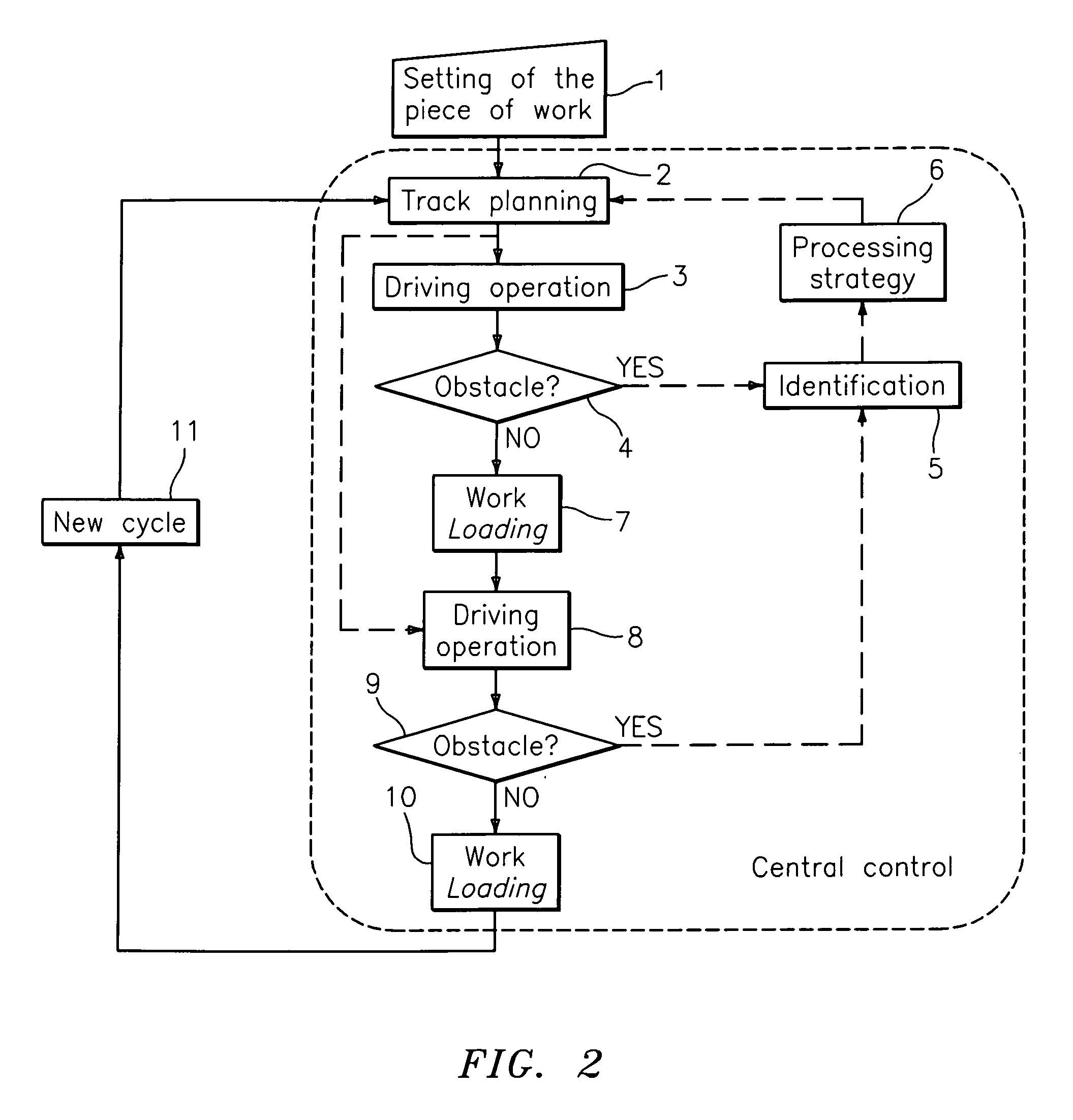
"The present invention is a system for the automatic movement of material in a working area. The system can automatically move and load back a piece of equipment in a working area. The system has improved efficiency in handling obstacles in the working area and can operate optimally even at night. The system uses positioning systems for detecting the effective location of the piece of equipment and eliminating obstacles in the working area. The movable piece of equipment has a tool to take up and transport material, which can be used to remove obstacles. The system makes use of the extended possibilities of the movable piece of equipment to eliminate obstacles in the working area. The control of the system has functions for automatically moving and removing obstacles, as well as a function for driving around obstacles. The system can continuously clean the travel paths and improve efficiency in the working area."

Problems solved by technology

Obstacles can, however, be present in the working area which impede the free movement of the piece of equipment.
Such obstacles can, for example, be stones or blocks which already spill over onto the shunting area or onto the travel paths on the material extraction such as in the blasting operation or which collect during the material transfer by material loss from the piece of equipment.
Furthermore, damage to the surface of the travel path such as potholes can represent obstacles since driving over such positions can damage the piece of equipment.

Method used


Image

  • System for the automatic movement of material
  • System for the automatic movement of material
  • System for the automatic movement of material

Examples


Embodiment Construction

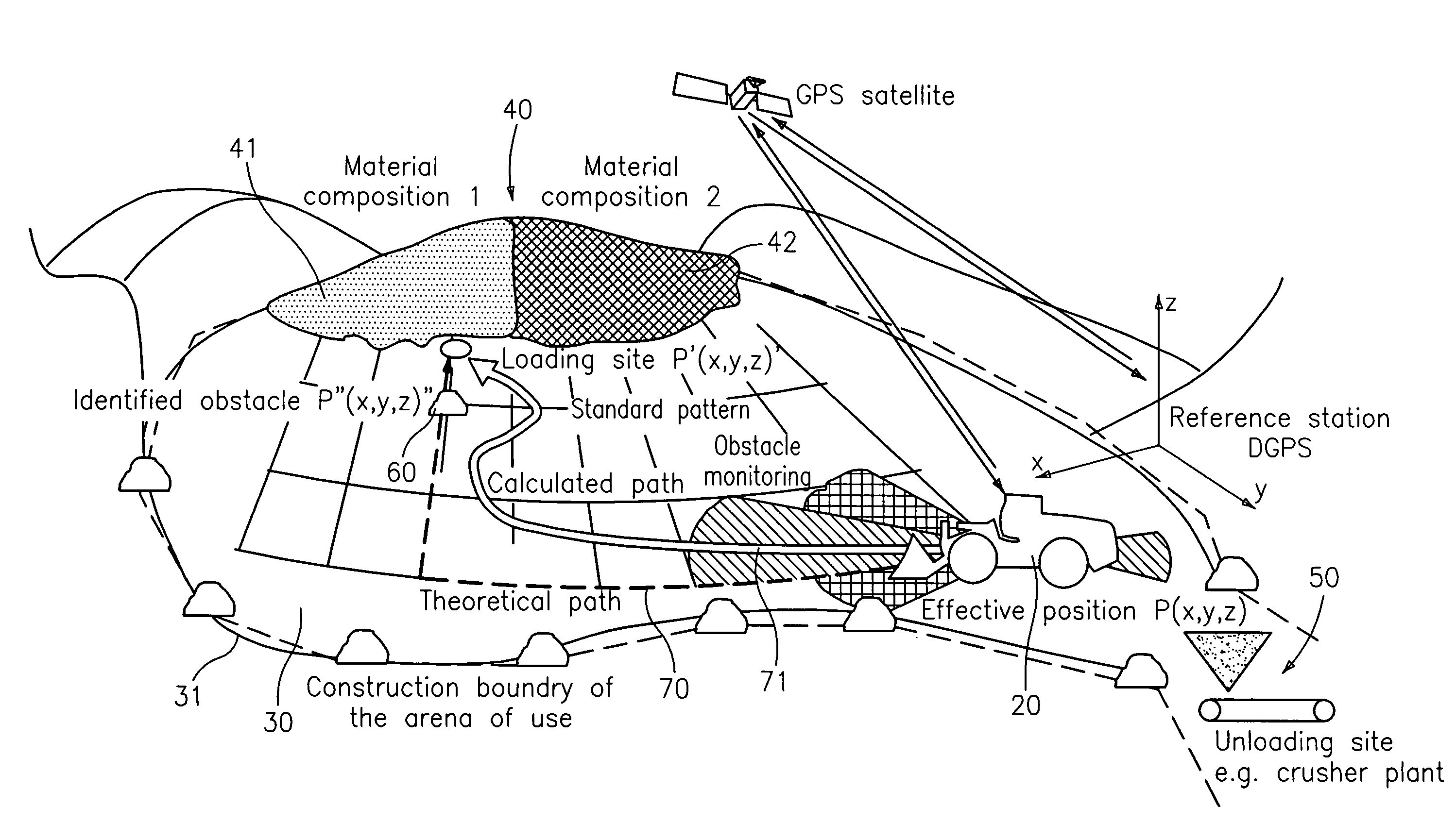
[0052]FIG. 1 shows a working area 30 into which one ore more autonomously working movable pieces of equipment 20 move, with the work process typically consisting of the loading, transporting and unloading of a bulk good.

[0053]The working area 30 is advantageously bounded by construction measures to prevent an uncontrolled passing over of these boundaries by the autonomously working pieces of equipment. This is e.g. ensured by a construction boundary 31 of the area of use. Furthermore, it is ensured by an enclosure that an ingress into the area by unauthorized persons during the automatic operation can be prevented.

[0054]The working area 30 typically consists of regions in which material is loaded from the excavated material, free areas which are negotiated in driving operation and one or more unloading sites 50 such as a funnel for the filling of a crusher or an area for the loading of trucks. The movable piece of equipment takes up material at a loading site 40 and transports it ov...


PUM


Abstract

The present invention relates to a system for the automatic movement of material in a working area comprising at least one movable piece of equipment, wherein the system has a control for the automatic movement of the piece of equipment with an automatic recognition of obstacles. In accordance with the invention, the control has a first obstacle processing function which moves an obstacle in the working area automatically using the movable piece of equipment; and / or in that the control has a second obstacle processing function which automatically removes an obstacle from the working area using the movable piece of equipment.

Description

BACKGROUND OF THE INVENTION[0001]The present invention relates to a system for the automatic movement of material in a working area comprising at least one movable piece of equipment, wherein the system has a control for the automatic movement of the piece of equipment with an automatic recognition of obstacles.[0002]Such a system is advantageously used in a working area in which the movable piece of equipment automatically loads material at one or more loading sites and unloads it again at one or more unloading sites. Free areas are usually disposed between the loading sites and the unloading sites which have to be negotiated in driving operation.[0003]The movable piece of equipment usually has a tool, in particular a bucket, which can advantageously be raised via a lifter and is moreover pivotable, for the taking up and transportation. In particular a wheeled loader is advantageously used as a movable piece of equipment in the system in accordance with the invention. In this conne...

Claims


Application Information

Patent Timeline
Patent Type & Authority Applications(United States)
IPC IPC(8): G05D1/00E02F3/04G08G1/16
CPCE02F1/00E02F9/2025E02F9/2045G05D1/0236G05D1/024G05D2201/0202G05D1/0251G05D1/0255G05D1/0257G05D1/0272G05D1/0278G05D1/0242E02F9/205E02F9/264
Inventor KIEGERL, CHRISTOPHUKIMERAJ, LEKEHUBER, MARKUS
Owner LIEBHERR WERK BISCHOFSHOFEN GES
Learn More