Roller support assemblies

a technology for supporting assemblies and rollers, which is applied in the direction of door/window fittings, multi-purpose tools, construction, etc., can solve the problems of significant risk of causing damage to the peripheral rim of the roller, and the service life is reduced, so as to minimize or prevent damage to the roller during installation, and improve the performance of the assembly once installed.

Active Publication Date: 2009-03-26
ANTHONY INNOVATIONS
View PDF7 Cites 7 Cited by
  • Summary
  • Abstract
  • Description
  • Claims
  • Application Information

AI Technical Summary

Benefits of technology

[0005]The objective of the present invention is to provide a roller support assembly that will improve performance of the assembly once installed and preferably minimize or prevent damage to the roller during installation.
[0011]It will be apparent from the foregoing that the roller support assembly provided according to this invention will have stronger and less flexible housing side walls as the side walls are not partially weakened by a rear opening into the lower edge of the housing to permit the roller to be installed therewith.
[0012]In accordance with a second aspect of this invention, there is provided a roller support assembly having a housing member having spaced apart housing side walls defining a roller receiving zone therebetween, a roller operationally supported in said roller receiving zone, said roller including a roller body, a shaft supporting said roller body for rotation relative to said shaft, and said shaft including stub shaft parts extending laterally from opposed side wall surfaces of said roller body, each said housing side wall having an opening for receiving and retaining a said stub shaft part when the roller is installed in said roller receiving zone, said housing member further including at least one transverse wall extending between said housing side walls, each of said side walls and the or each transverse wall having lower edge zones such that at least the lower edge zones of the housing side walls are arranged at or below a lower most extremity of said roller when the roller is installed in said roller receiving zone, and the lower edge zone of the or each said transverse wall being spaced upwardly from said lower edge zones of the housing side walls. In this embodiment the opening in the side walls of the housing might either be a fully enclosed opening or a recess opening onto the lower most edge of the side walls. In this second aspect, the provision of the side wall edge zones being extended to a position equal to or lower than the lower most extremity of the roller protects the roller during the installation process.

Problems solved by technology

While such assemblies have worked satisfactorily, the downwardly open retainer recesses in the side walls of the bogie member provide a degree of weakness and therefore greater flexibility for the side walls that are made from moulded plastics material, which can cause difficulties and lower service life when under reasonably heavy loads.
A further practical difficulty is that in roller support assemblies as described, the peripheral formed rim of the roller (or rollers) extends below the lower edge of the door or other panel in which it has been installed.
There is then a risk that the door or other panel will, during installation and before the roller is correctly engaged with the linear guide track on which it is intended to roll, will be supported on the roller peripheral rim and possibly dragged across surfaces transverse to the peripheral rim.
Given that the roller body and the formed peripheral rim are commonly also made from moulded plastics material, such actions during installation have a significant risk of causing damage to the peripheral rim of the roller.

Method used


Image

  • Roller support assemblies
  • Roller support assemblies
  • Roller support assemblies

Examples


Embodiment Construction

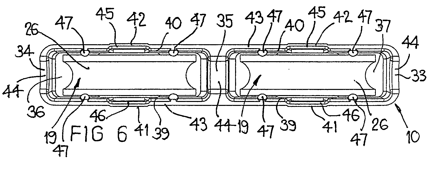
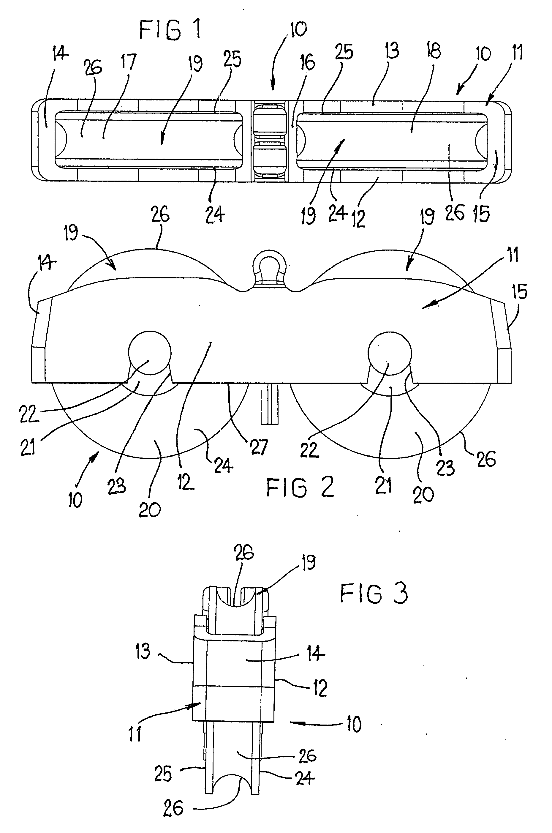
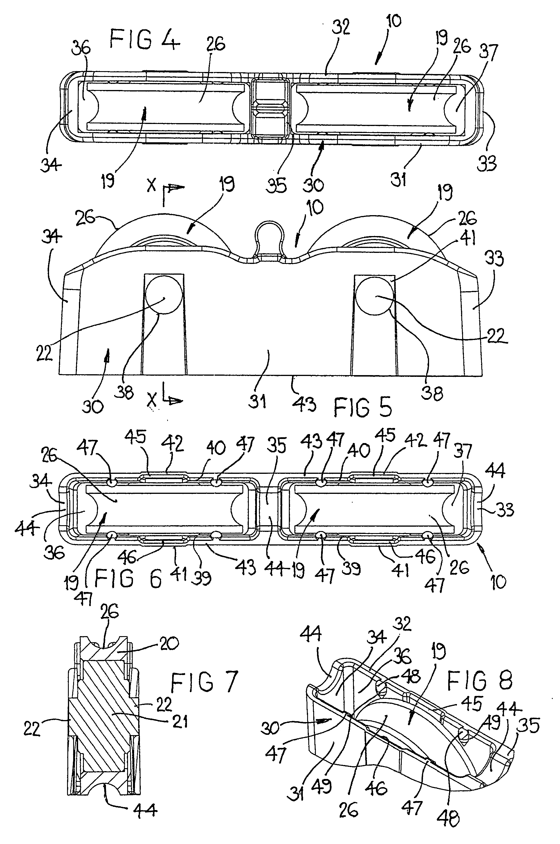
[0023]Referring first to FIGS. 1 to 3, there is shown a bogie arrangement 10 usable in a roller support assembly of the general type described and illustrated in Australian Patent Specification No. 779340. The prior art assembly comprises a housing member 11 with a pair of spaced side walls 12, 13, a pair of transverse end walls 14, 15 integrally formed with and interconnecting the side walls 12, 13 and an intermediate transverse wall 16 dividing the space within the housing member 11 into two roller receiving zones 17, 18, each having a roller assembly 19 mounted therein. Each roller assembly 19 includes a roller body 20, a shaft 21 with stub shaft parts 22 extending laterally from side faces 24, 25 of the roller body 20. The roller body has a peripheral rim 26 formed as a groove so as to be cooperable, in use, with a linear guide track (not shown). The roller body 20 is rotationally mounted on the shaft 21 and each roller assembly 19 is secured to the housing member 11 by snap fit...


PUM


Abstract

A roller support assembly is used to support sliding doors, windows or the like. The assembly includes a housing member having spaced apart side walls and interconnecting transverse walls defining a roller receiving zone for receiving and operationally mounting a roller assembly. The roller assembly has a roller body with a rolling peripheral rim and a shaft whereby the roller body is rotatable relative to the shaft having short stub axle parts. The housing side walls including openings that are fully enclosed by the side walls into which the short stub axle parts fit. The housing side walls further include projecting elements extending inwardly from an inner surface of a housing side wall to cooperate with the corresponding roller body side wall surfaces to spay the housing side walls apart as the roller assembly is moved into the roller receiving zone to locate the stub axle parts in the openings.

Description

FIELD OF THE INVENTION[0001]The present invention relates to roller support assemblies or structures for supporting sliding doors, windows or the like.BACKGROUND OF THE INVENTION[0002]Commonly rollers used in support structures have a roller body with a peripheral formed rim adapted in use to engage a linear guide track to roll there along. The rollers commonly include an axially extending shaft with suitable bearing means to allow the roller body to freely rotate about a rotation axis defined by the shaft with the shaft having short axially extending stub shaft parts extending outwardly of side walls of the roller body. The short stub shaft parts are adapted to engage and be retained in a downwardly open retainer recess in side walls of a housing part of some form, the minimum dimension of the recess being slightly less than that of the stub shaft parts such that the stub shaft parts will, when being assembled snap fit into the retainer recess and be held thereby.[0003]Typically, t...

Claims


Application Information

Patent Timeline
Patent Type & Authority Applications(United States)
IPC IPC(8): E05D15/06
CPCE05D15/063E05D15/0665E05Y2201/64E05Y2201/688E05Y2600/32E05Y2600/52Y10T16/216E05Y2900/132Y10T16/384Y10T16/381Y10T16/205Y10T16/3837E05Y2900/148
Inventor PROCTOR, NIGELLAZZARIN, PAOLOJEFFERSON, DEREK
Owner ANTHONY INNOVATIONS
Why Eureka
Try Eureka