Method of Matching Sensors in a Multi-Probe Turbine Blade Vibration Monitor

a technology of vibration monitor and sensor, which is applied in the direction of instruments, specific gravity measurement, furniture, etc., can solve the problems of spectral noise, error, and inability to ensure the measurement, and achieve the effect of ensuring the measurement and ensuring the accuracy of the measuremen

Inactive Publication Date: 2009-03-26
SIEMENS ENERGY INC
View PDF29 Cites 26 Cited by
  • Summary
  • Abstract
  • Description
  • Claims
  • Application Information

AI Technical Summary

Problems solved by technology

Due to their complex design, natural resonant mechanical frequencies of the blades may coincide with or be excited by certain blade rotational speeds and rotational harmonics thereof.
However, when multiple sensors are used, there is typically no way to ensure that all of the sensors are exactly coplanar with the blade row.
That is, the sensors may be misaligned relative to each other axially in a direction parallel to the axis of rotation of the blades, such that the sensors do not all sense the same location on the blade tip.
Thus, while the blade pass signal is sampled multiple times each revolution, there is an error that is introduced in this sampling due to misalignment of the sensors and slight variances in the electrical performance of each sensor.
This results in an error and spectral noise in the measurement.

Method used


Image

  • Method of Matching Sensors in a Multi-Probe Turbine Blade Vibration Monitor
  • Method of Matching Sensors in a Multi-Probe Turbine Blade Vibration Monitor
  • Method of Matching Sensors in a Multi-Probe Turbine Blade Vibration Monitor

Examples


Embodiment Construction

[0023]In the following detailed description of the preferred embodiment, reference is made to the accompanying drawings that form a part hereof, and in which is shown by way of illustration, and not by way of limitation, a specific preferred embodiment in which the invention may be practiced. It is to be understood that other embodiments may be utilized and that changes may be made without departing from the spirit and scope of the present invention.

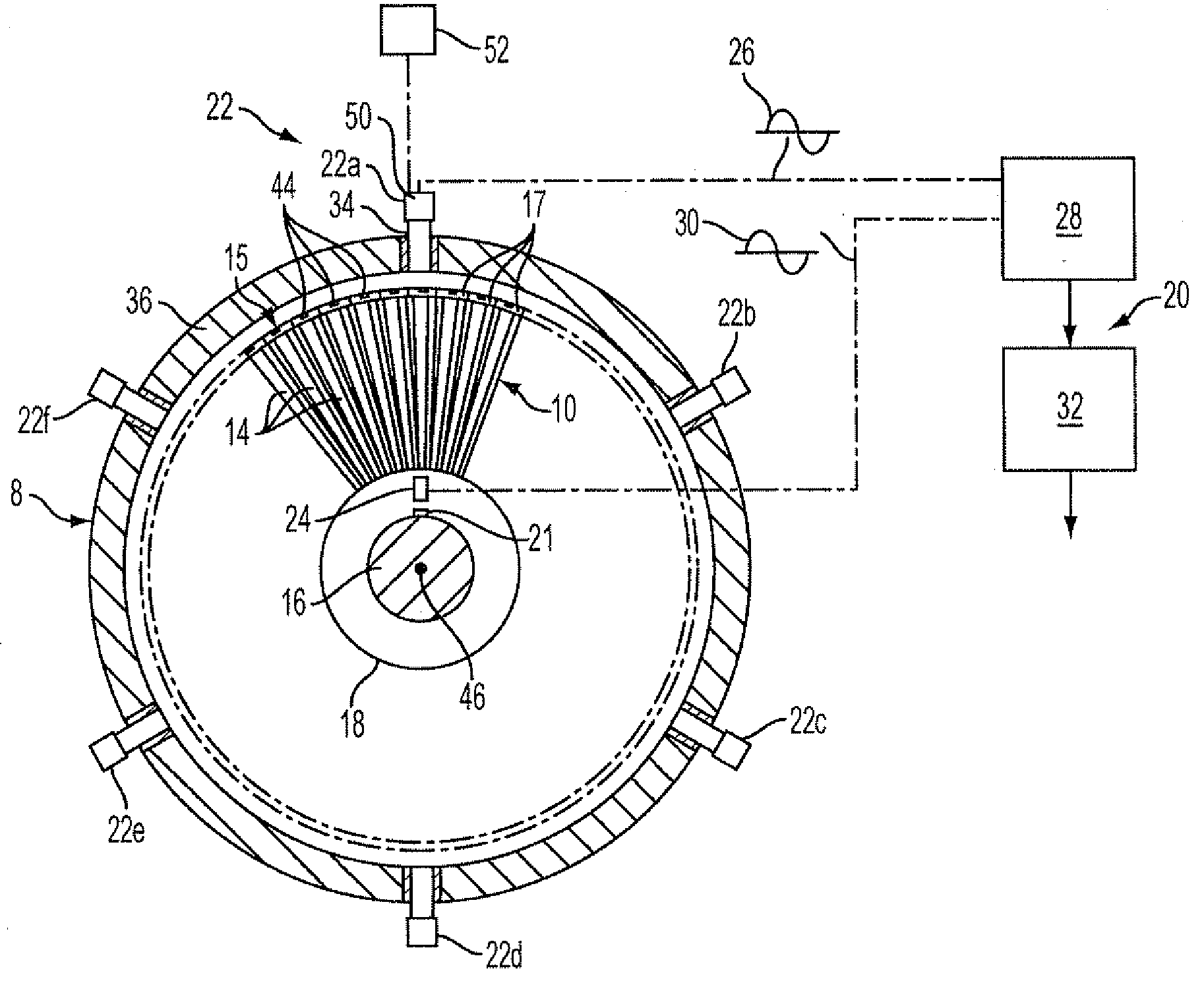
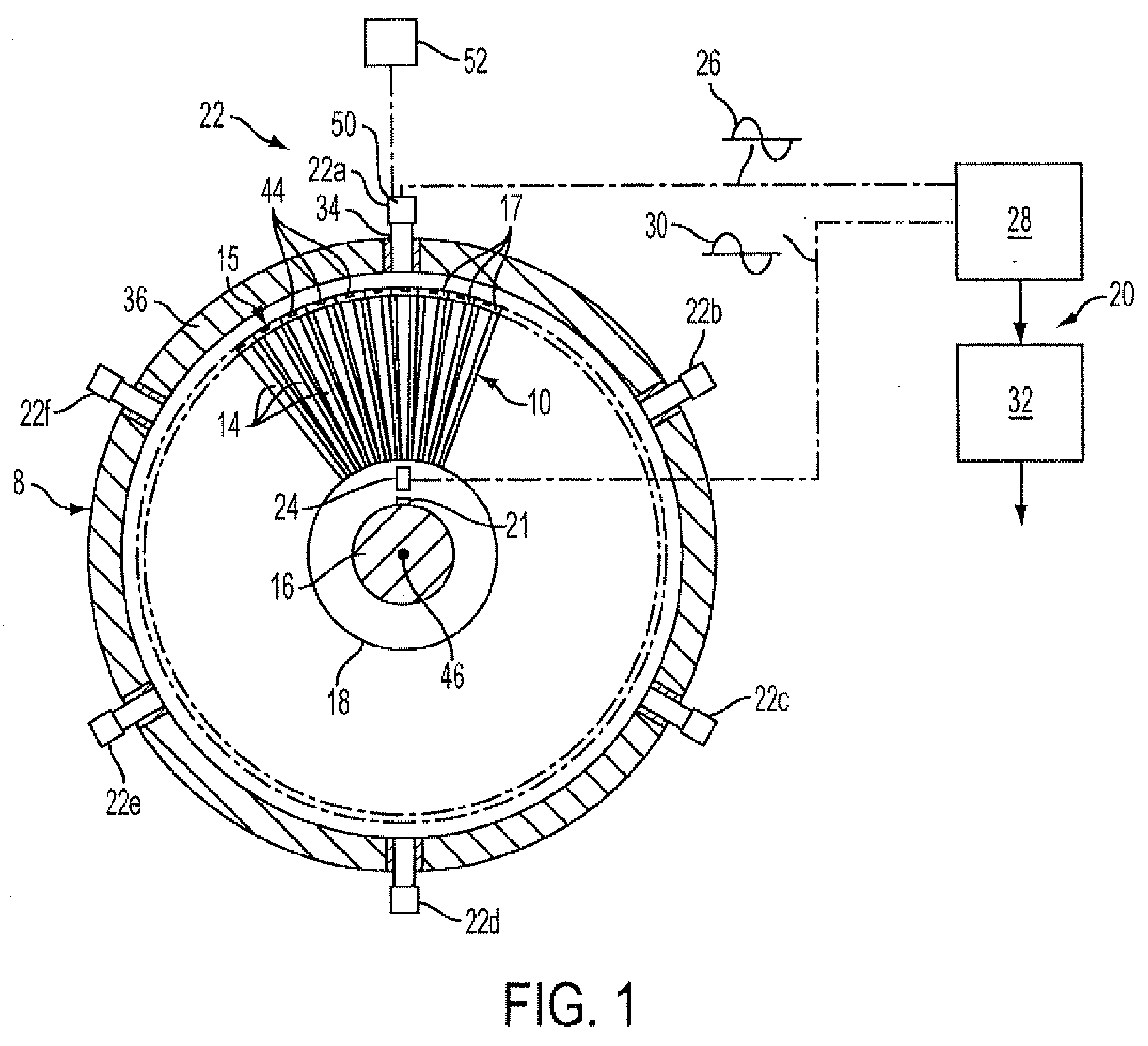
[0024]FIG. 1 diagrammatically illustrates a turbine 8 including a shrouded turbine blade row 10 in which the method of the present invention can be employed in a blade vibration monitoring system to monitor nonsynchronous turbine blade vibrations. Turbine blades 14 are connected to a rotor 16 by means of a rotor disk 18. Outer ends of the turbine blades 14 are interconnected by a circumferential outer shroud 15 defined by a plurality of shroud sections 17 attached to the blades 14.

[0025]A nonsynchronous turbine blade shroud vibration mon...


PUM


Abstract

A method of matching sensors in a multi-probe blade vibration monitor for a turbine. The method includes providing at least two probes mounted in a casing of the turbine adjacent to a rotating blade structure of the turbine. Targets are provided on radially outer portions of the blade structure. Each of the probes includes a sensor generating signals corresponding to target passing events, and a set of synchronous harmonics of the rotational speed of the rotor are produced for each sensor. The position of the sensors is adjusted such that the sets of harmonics of the sensors are substantially matched, indicating that the positions of the sensors are matched.

Description

[0001]This application claims priority to a provisional application filed on Sep. 21, 2007, having application No. 60 / 974,134, which is incorporated herein by reference.FIELD OF THE INVENTION[0002]The present invention relates to a method of monitoring a blade structure in a turbine and, more particularly, to a method of positioning sensors in a multi-probe blade vibration monitor for a turbine such that the sensors are located at the same axial location relative to the blade structure.BACKGROUND OF THE INVENTION[0003]A high speed turbo machine, such as, for example, a steam or gas turbine, generally comprises a plurality of blades arranged in axially oriented rows, the rows of blades being rotated in response to the force of a high pressure fluid flowing axially through the machine. Due to their complex design, natural resonant mechanical frequencies of the blades may coincide with or be excited by certain blade rotational speeds and rotational harmonics thereof. To prevent excessi...

Claims


Application Information

Patent Timeline
Patent Type & Authority Applications(United States)
IPC IPC(8): G01H1/06
CPCG01H1/08G01H1/003
Inventor TWERDOCHLIB, MICHAEL
Owner SIEMENS ENERGY INC
Why Eureka
Try Eureka