Valve with Thin-Film Coating

a technology of thin film coating and valve seat, which is applied in the direction of machines/engines, soldering devices, applications, etc., can solve the problems of affecting the performance of the valve, affecting the wear of the valve body and/or the valve seat during use, and producing unacceptably high wear rates

Active Publication Date: 2009-03-26
CATERPILLAR INC
View PDF21 Cites 16 Cited by
  • Summary
  • Abstract
  • Description
  • Claims
  • Application Information

AI Technical Summary

Problems solved by technology

This in turn affects the performance of the valve and also may affect how the valve body and/or valve seat wear during use.
For example, the valve plate and valve seat may be produced from materials that will produce unacceptably high wear rates in the use of certain new...

Method used


Image

  • Valve with Thin-Film Coating
  • Valve with Thin-Film Coating
  • Valve with Thin-Film Coating

Examples


Embodiment Construction

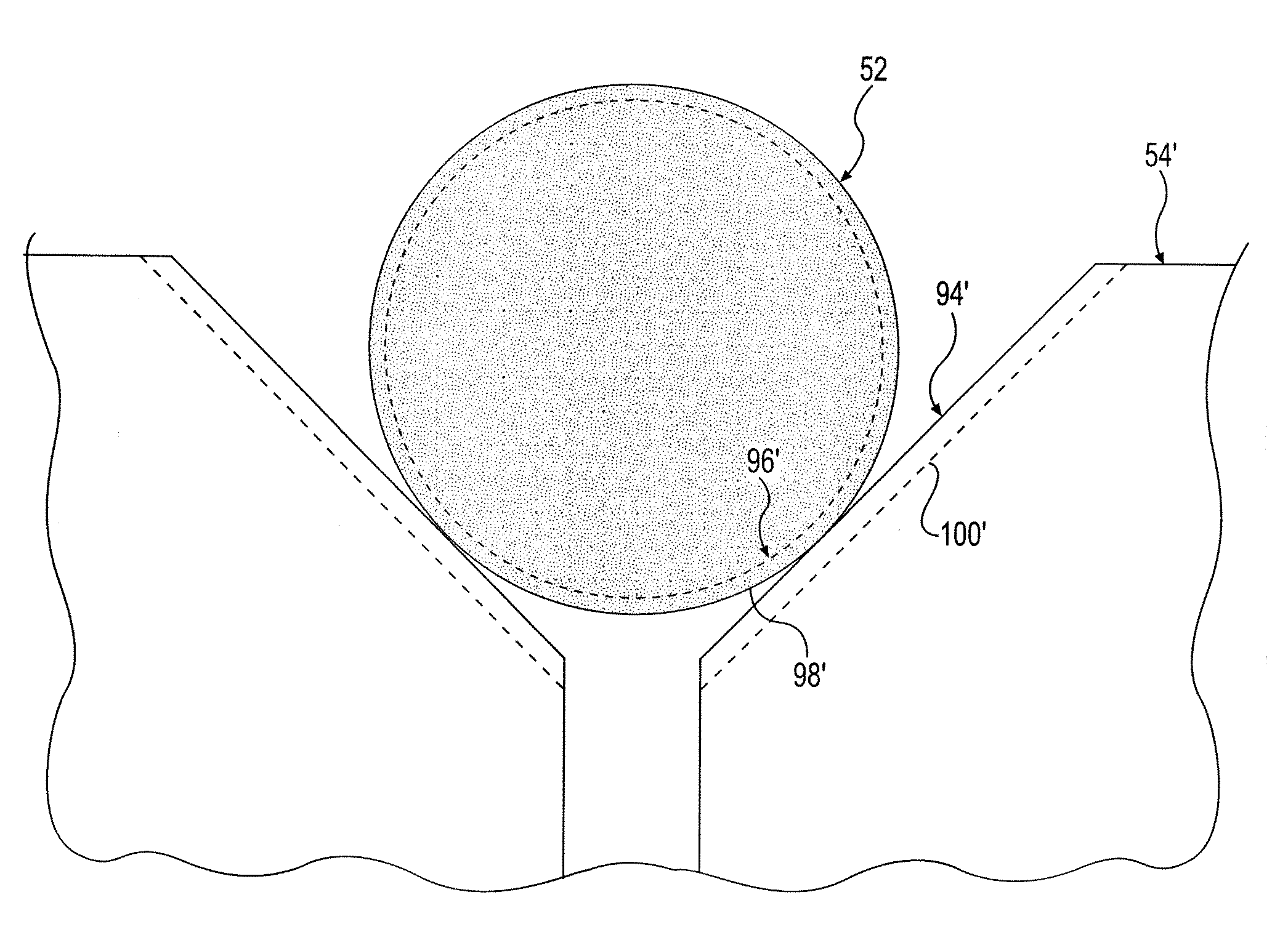
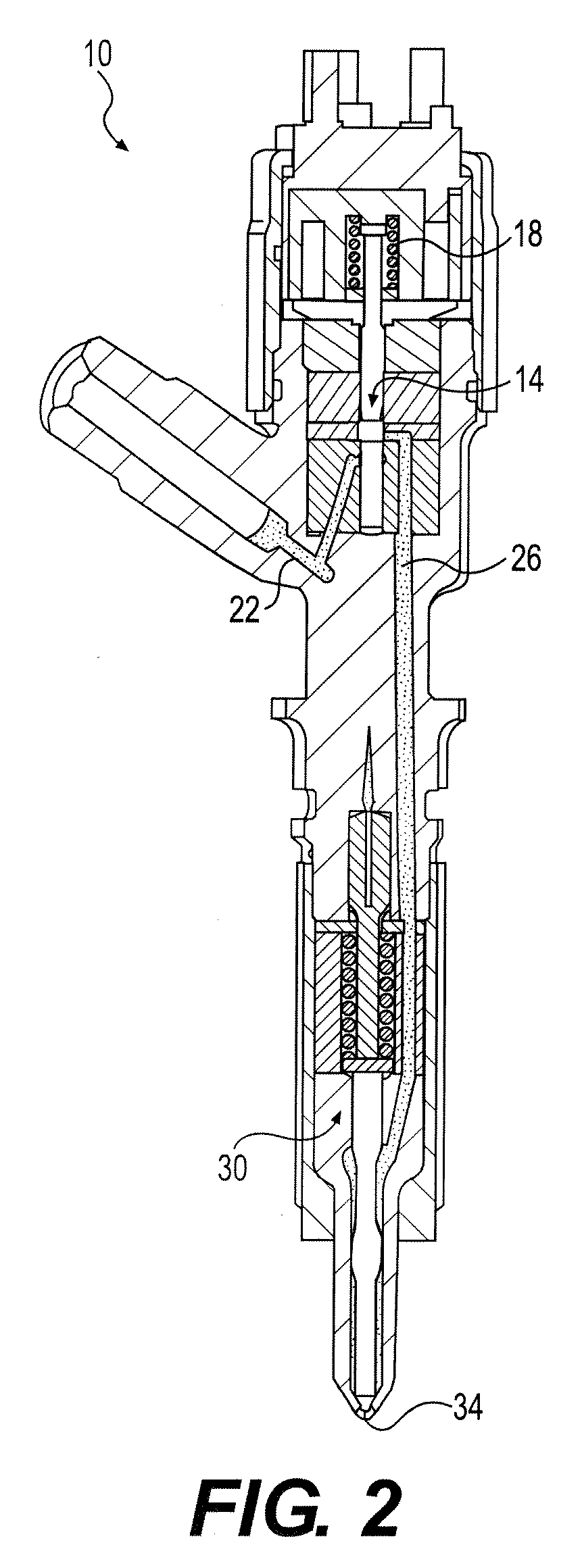
[0022]FIG. 1 illustrates a fuel system component according to an exemplary embodiment. As described in detail below, the component can include at least one valve body configured to engage a valve seat to control fluid flow through a valve. Further, in some embodiments, the body and seat will be configured to repeatedly engage one another to produce impact between opposing surfaces of the valve body and seat. In addition, the opposing surfaces of the valve body and seat may include hard coatings configured to reduce wear caused by repeated engagement of the valve body and seat.

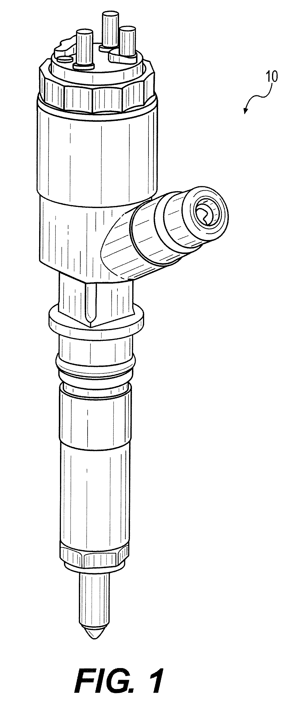
[0023]As shown, the component includes a fuel injector 10, as may be used with diesel or gasoline engines. However, it will be appreciated that the fuel system components of the present disclosure may be used with other fuel systems for other engine types, and with different types of fuel injectors in which it may be desirable to control wear between opposing valve surfaces (e.g., a common rail injector system)...


PUM

PropertyMeasurementUnit
Angleaaaaaaaaaa

Abstract

A fuel system component is provided. The fuel system component may comprise a valve body having a substantially conical surface region including a first coating. The component may further include a valve seat having a first surface region with a substantially conical surface including a second coating. The coating of the valve seat is configured to engage at least a portion of the coating of the substantially conical surface region of the valve body.

Description

TECHNICAL FIELD[0001]This disclosure pertains generally to fuel system components, and more particularly, to fuel system components having thin-film coatings.BACKGROUND[0002]Many internal combustion engines, whether compression ignition or spark ignition engines, use fuel injection systems to provide precise and reliable fuel delivery into the combustion chamber of the engine. Such precision and reliability are necessary to address the goals of improved fuel efficiency, maximum power output, and reduction of undesirable emissions. Generally, fuel systems will include a fuel pump and one or more fuel injectors. The fuel pump will supply fuel to the injectors, which will subsequently provide precise control of the fuel supply and timing to engine cylinders.[0003]Traditionally, hard coatings can be applied to components of fuel systems to reduce wear and / or prevent corrosion. For example, where opposing parts contact one another, a coating may be used to reduce wear between the compone...

Claims


Application Information

Patent Timeline
IPC IPC(8): F16K25/00
CPCF02M61/18F02M61/1886Y10T29/49405F02M2200/9038F02M61/1893Y10T137/7036
Inventor SHAFER, SCOTT F.MOORE, BRYAN
Owner CATERPILLAR INC
Why Eureka
Try Eureka