Filtered cathodic-arc plasma source

a cathodic arc and plasma source technology, applied in the direction of vacuum evaporation coating, electrolysis components, coatings, etc., can solve the problems of affecting the application of vacuum arc technology, deterioration especially affects such demands, and deterioration of the quality of the synthesized coating and the surface treated in this manner, so as to reduce the kinetic ion energy

Inactive Publication Date: 2007-08-16
THE UNITED STATES OF AMERICA AS REPRESETNED BY THE SEC OF THE AIR FORCE
View PDF14 Cites 70 Cited by
  • Summary
  • Abstract
  • Description
  • Claims
  • Application Information

AI Technical Summary

Benefits of technology

[0095] The field configuration in zone 22 is known as an acute-angled or cusped magnetic-electric trap. The electrons received from the source 1 can escape from this trap through axial cusps along the plasma ducts 11, 12 and 9 and through the annular cusp (magnetic slit) 23. The field strength of the magnetic coils contributing to the zone 22 are chosen such that in the axial cusps along the plasma ducts 11 and 12, and also in the slit 23, the fields form magnetic mirrors that prevent electron pass through. Only an insignificant part of electrons moving immediately along the central lines of the cusps in the plasma ducts 11, 12 and in the slit 23 may thus leave the trap. The only channel where the electrons may go unimpeded along the magnetic field lines is the part of the

Problems solved by technology

These processes form desirable coatings and surface layers that cannot be produced by other known methods.
The presence of macroparticles of cathode material in cathodic-arc plasma often deteriorates the quality of a synthesized coating and a surface treated in this manner.
This deterioration in fact hinders an even wider application of the vacuum arc technology.
This deterioration especially affects such demanding applications as microelectronics, optics, fine mechanics, and medicine (e.g. surgical instrument sets and prosthetics).
The output of the useful (ion) plasma component is however moderate in this device because of great ion losses on the incorporated screen.
In these systems however, the losses of the ion component are increased and the throughput of the plasma stream is significantly decreased.
The productivity of such systems is reduced, while design complexity and, correspondingly, costs are increased.
As a result, the applicability of these systems in the coating production practice is rather limited.
These simplifications in filter design are

Method used


Image

  • Filtered cathodic-arc plasma source
  • Filtered cathodic-arc plasma source
  • Filtered cathodic-arc plasma source

Examples


examples

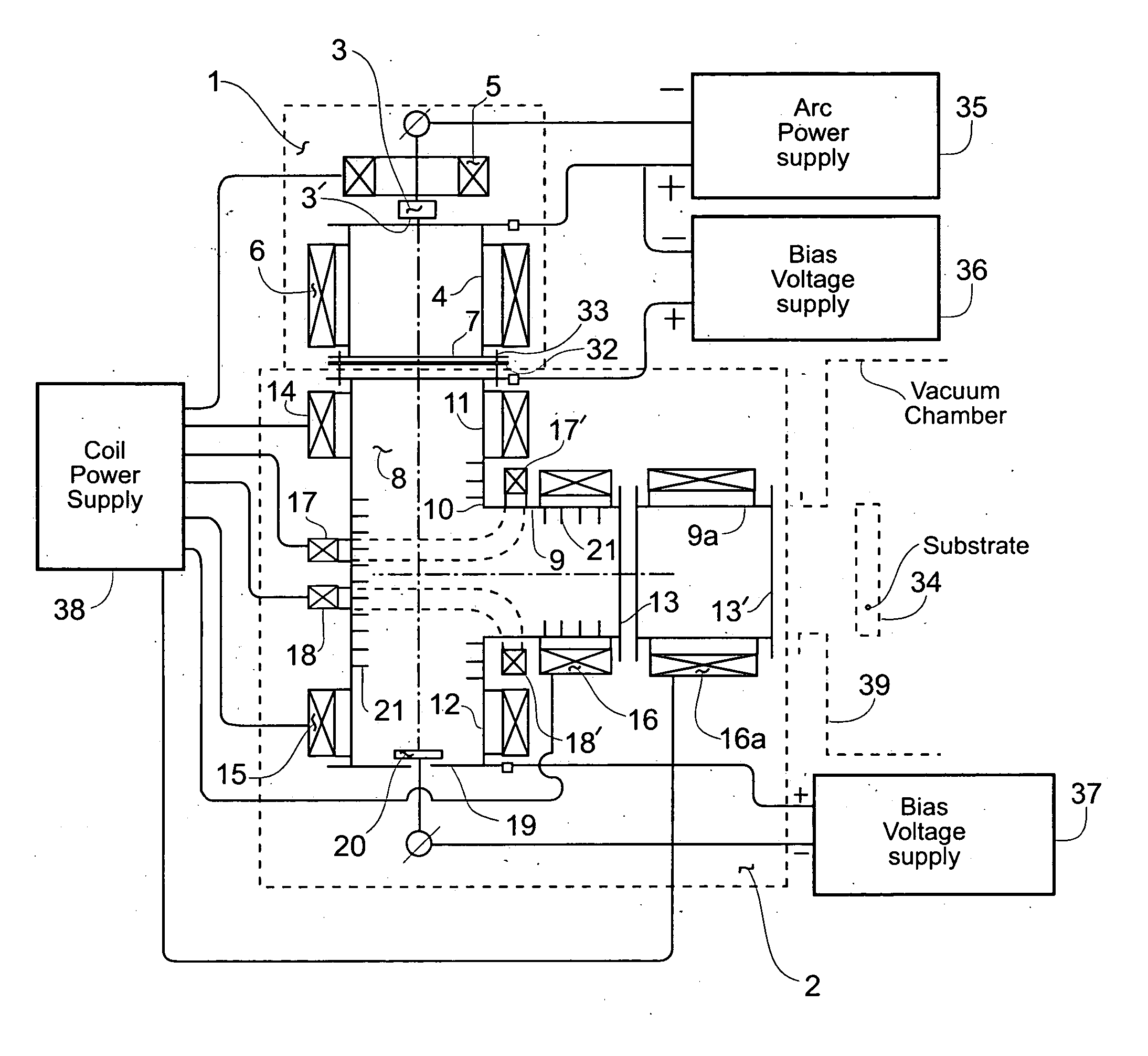
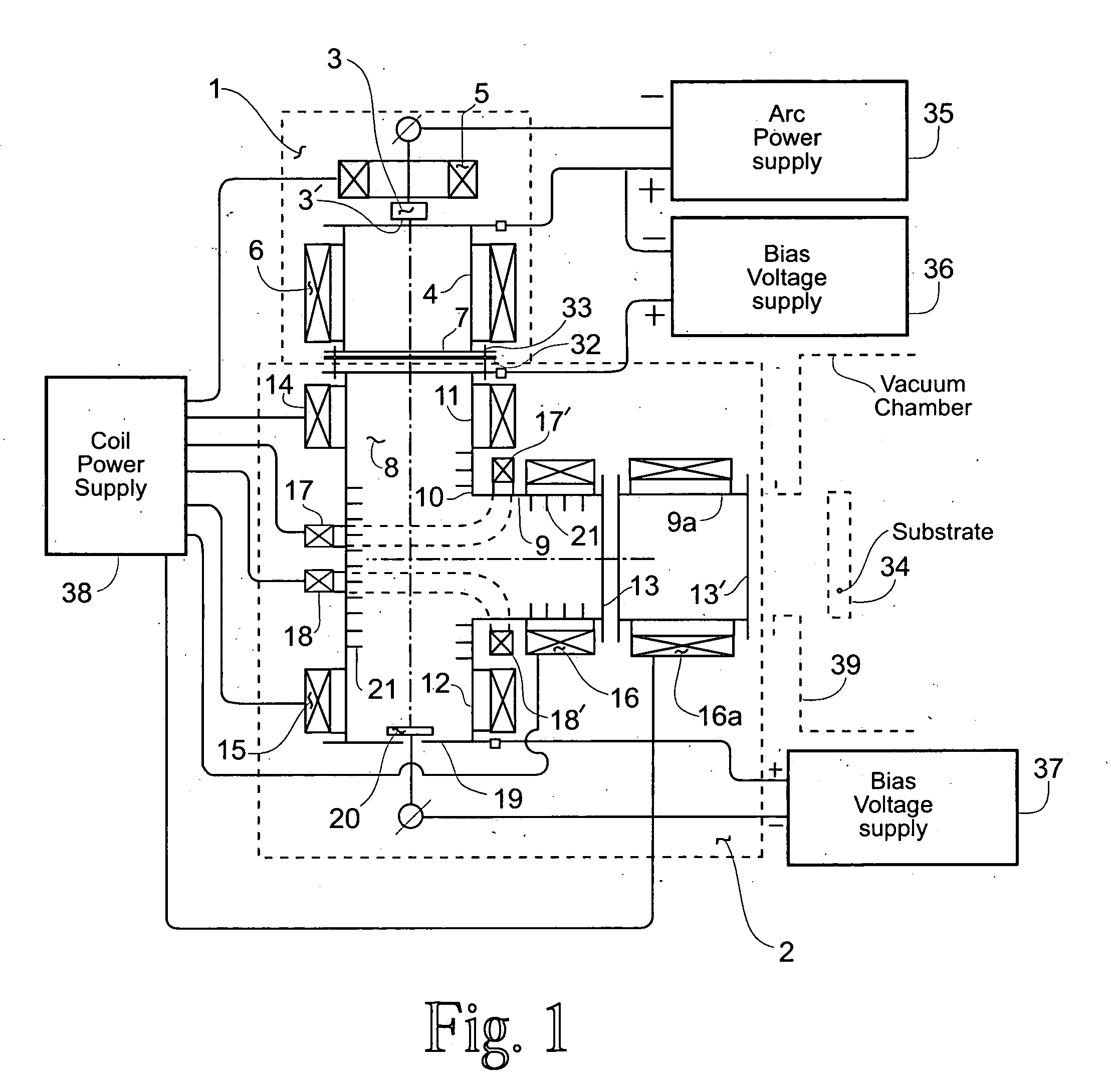
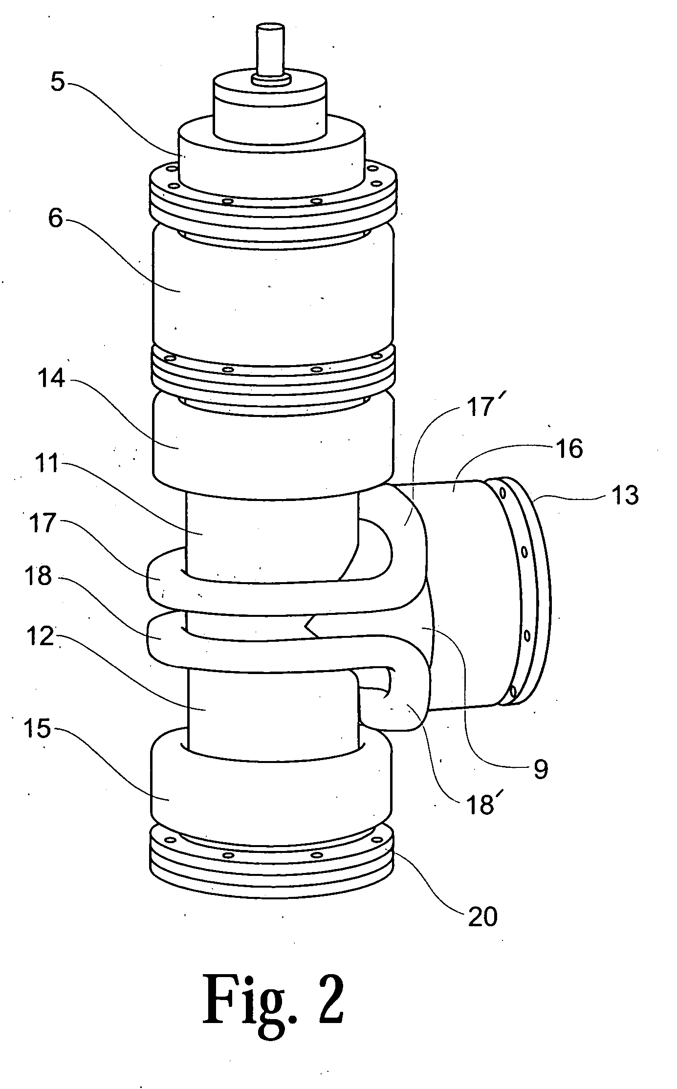
[0112] A test model of the present invention filtered cathodic-arc plasma source according to the arrangement shown in FIG. 5 may be considered as exemplary. In this source the cathode 3 of plasma generator 1 may be a cylinder, 60 millimeters in diameter of Titanium cathode material. The non-working end of the cathode, the anode and the plasma ducts are preferably cooled with water. The anode and all plasma ducts may be made from a nonmagnetic stainless steel. The inner diameter of anode 4 and plasma ducts 8 and 9 may be 190 millimeters. The anode length may be 200 millimeters and the length of each of plasma-guiding channel element 11, 12, 9, 9′ made 190 millimeters. The number of Ampere-turns in the magnetic coils of the system may be such as provide the magnetic field distribution shown in FIG. 6 at a field intensity of 50 Oersteds on the axis of the output plasma duct 9. Typical Ampere-turns characteristics for the magnetic coils 5, 6, 14, 15, 16, 16a, 17, 18 and 24 are 2000, 10...


PUM

PropertyMeasurementUnit
Polarityaaaaaaaaaa
Diameteraaaaaaaaaa
Magnetic fieldaaaaaaaaaa

Abstract

A filtered cathodic-arc plasma source of lower plasma losses and higher output plasma current to input current efficiency is disclosed. Plasma filtering is accomplished in a right angle bend magnetic filter arranged to include the effects of at least three added magnetic coils located at the right angle bend of the filter path. These magnetic coils and other filter attributes, including an array of transverse fins and a magnetic cusp trap in the filter path, achieve desirable magnetic flux paths, lower plasma collision losses and reduced undesired particle output from the plasma filter. Multiple cathode sources, multiple plasma output ports, Larmour radius influence, equipotential magnetic flux lines and electron/ion interaction considerations are also included in the plasma source. Application of the plasma source to film coating processes is included.

Description

RIGHTS OF THE GOVERNMENT [0001] The invention described herein may be manufactured and used by or for the Government of the United States for all governmental purposes without the payment of any royalty. BACKGROUND OF THE INVENTION [0002] This invention concerns ion-plasma treatment of materials and, more particularly filtered high quality cathodic-arc plasma sources usable for such treatment. [0003] Vacuum-arc methods of coating deposition and surface modification have gained wide recognition in recent decades for use in for example tool production, mechanical engineering and instrument making. These processes form desirable coatings and surface layers that cannot be produced by other known methods. The essence of and the areas of application of vacuum-arc coating formation and surface modification have been described for example in the technical journal articles “Principles and Applications of Vacuum Arc Coatings” by R. L. Boxman, IEEE Transactions on Plasma Science, Volume 17, Nu...

Claims


Application Information

Patent Timeline
IPC IPC(8): C23C14/32C23C14/00H01J37/32
CPCH01J37/32055H01J2237/022H01J37/3266H01J37/32633
Inventor AKSENOV, IVAN I.STRELNYTSKIY, VOLODYMYR E.VASYLYEV, VOLODYMYR V.VOEVODIN, ANDREY A.JONES, JOHN G.ZABINSKI, JEFFREY S.
Owner THE UNITED STATES OF AMERICA AS REPRESETNED BY THE SEC OF THE AIR FORCE
Why Eureka
Try Eureka