Ion transmission interface device

A technology for ion transmission and interface devices, which is applied in ion sources/guns, parts of particle separator tubes, mass spectrometers, etc., and can solve problems such as low ion transmission efficiency, great influence on mass spectrometer sensitivity, and prolonging the working time of equipment , to achieve high ion transmission efficiency, good sensitivity, and improve transmission efficiency

Pending Publication Date: 2019-11-29
广州质谱技术有限公司
View PDF0 Cites 2 Cited by
  • Summary
  • Abstract
  • Description
  • Claims
  • Application Information

AI Technical Summary

Problems solved by technology

[0002] Atmospheric pressure ion sources used in existing triple quadrupole mass spectrometers are generally electrospray ion source ESI and atmospheric pressure chemical ion source APCI. The sensitivity of the mass spectrometer is greatly affected
[0003] In traditional ion transmission, in order to prevent uncharged particles and other impurities from entering the interface device, the ion source usually sends charged ions directly into the interface device i

Method used


Image

  • Ion transmission interface device
  • Ion transmission interface device
  • Ion transmission interface device

Examples


Embodiment Construction

[0034] The embodiments of the present invention will be described in detail below.

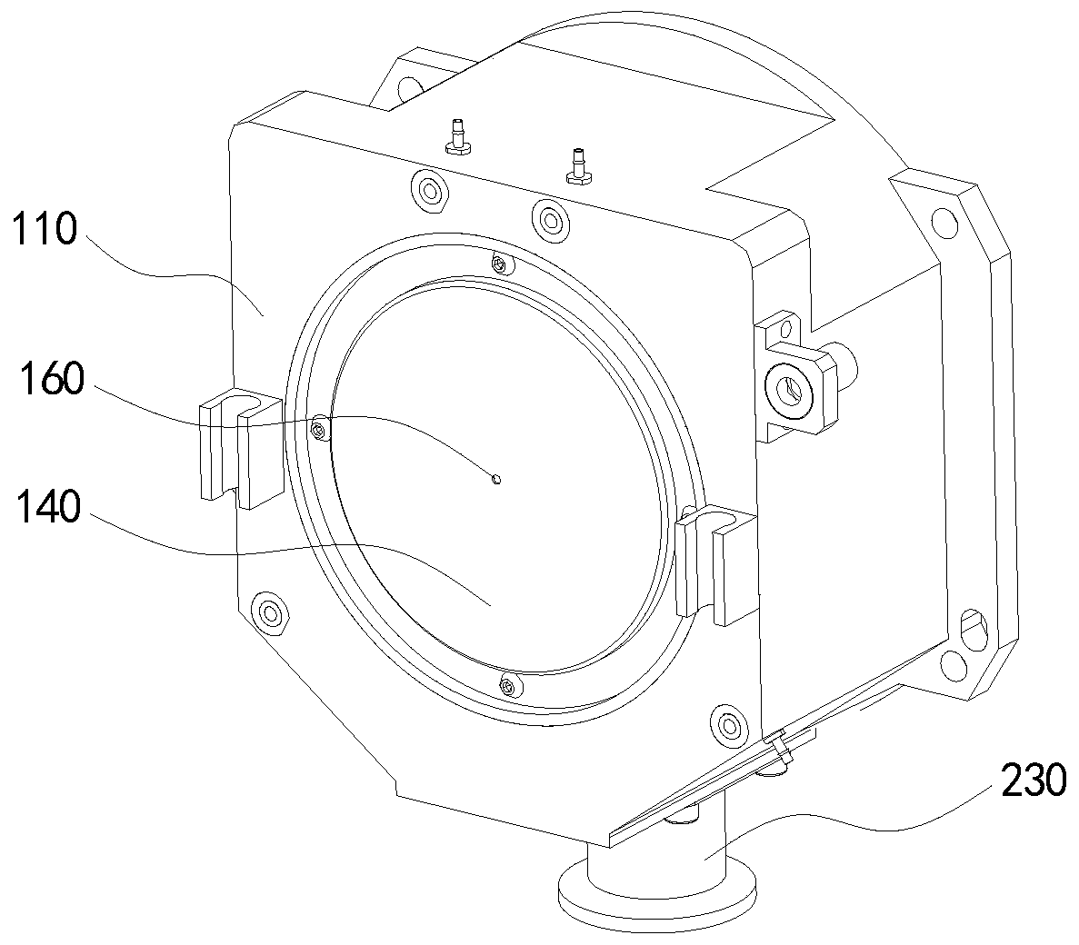
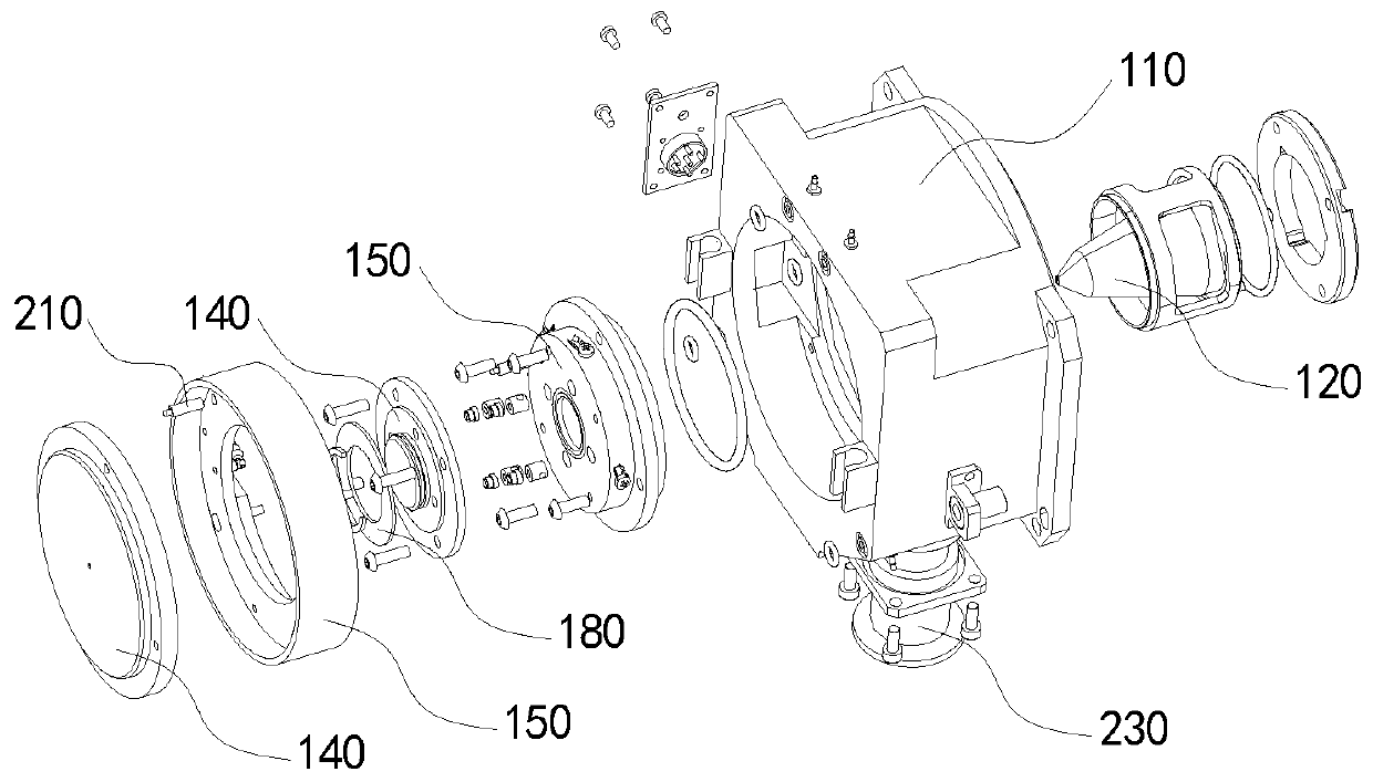
[0035] Such as figure 1 , figure 2 As shown, the ion transmission interface device of this embodiment has a casing, a separation cone, and an ion channel 130. The casing is a vacuum chamber environment for the transmission of charged ions in the entire ion transmission interface device. The insulating plate 150 serves as a conductive plate. The 140 mounting base is used to fix the conductive plate 140 to ensure the stable transmission of charged ions in the ion transmission hole 160 and the separation cone. The electric field of the conductive plate 140 attracts the charged ions and causes the charged ions to follow the gradient of the potential difference. The ion transmission hole 160 is transmitted to the ion channel 130.

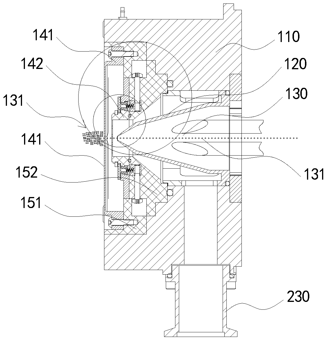
[0036] See next image 3 In this embodiment, the potential difference gradually decreases along the direction of the first conductive plate 141 to the second conductive plat...


PUM


Abstract

The invention discloses an ion transmission interface device, and the device comprises a shell, a separation cone, an ion channel, a conductive plate and an insulating plate; the shell is used for providing a vacuum cavity environment for transmission of charged ions; the separation cone is used for guiding charged ions to enter the ion channel; the conductive plate is mounted on the insulating plate; the ion transmission hole of the conductive plate and the ion transmission hole of the insulating plate are in the same horizontal line, and the direction of the separation cone faces the ion transmission hole; the potential difference between the conductive plate and the separation cone is gradually decreased in the direction from the conductive plate to the separation cone, and charged ionssequentially penetrate through the conductive plate, the insulating plate and the separation cone through the ion transmission hole according to the gradient of the potential difference and enter theion channel. The technical problem to be solved by the invention is to improve the ion transmission efficiency of charged ions from an ion source to an ion channel while preventing uncharged particles and other impurities from entering an ion transmission hole, thereby improving the sensitivity of a mass spectrometer.

Description

Technical field [0001] The invention relates to the technical field of mass spectrometry equipment, in particular to an ion transmission interface device. Background technique [0002] The atmospheric pressure ion source used in the existing triple quadrupole mass spectrometer is generally an electrospray ion source ESI and an atmospheric pressure chemical ion source APCI. The ion transmission loss rate of charged ions from the ion source to the interface device to the vacuum ion channel is The sensitivity of the mass spectrometer has a greater impact. [0003] In traditional ion transmission, in order to prevent uncharged particles and other impurities from entering the interface device, the ion source usually directly sends charged ions into the interface device in a vertical manner when spraying. However, the ion transmission efficiency of this method is low and will Some charged ions did not enter the interface device, resulting in a decrease in the sensitivity of the mass spe...

Claims


Application Information

Patent Timeline
IPC IPC(8): H01J49/26H01J49/10H01J49/02
CPCH01J49/02H01J49/10H01J49/26
Inventor 史志强
Owner 广州质谱技术有限公司
Why Eureka
Try Eureka