Solid-state image capturing device, solid-state image capturing apparatus, and electronic information device

a technology of solid-state image capturing and image capturing apparatus, which is applied in the direction of solid-state devices, color televisions, television systems, etc., can solve the problems of ineffective correction effect and conventional solid-state image capturing apparatus described above, and achieve the effect of shortening the design period and lowering the design cos

Active Publication Date: 2009-03-26
SHARP KK
View PDF0 Cites 15 Cited by
  • Summary
  • Abstract
  • Description
  • Claims
  • Application Information

AI Technical Summary

Benefits of technology

[0059]As described above, the present invention makes it possible to arrange at least any of microlenses, color filters and openings of electrode wiring layers in relation to various output angles of an image capturing optical system (incident angle from the image capturing optical system) in such a manner to continuously shift them in relation to respective light receiving elements in a light receiving region by a function based on Snell's law, thereby obtaining a good image without color shading or luminance shading due to the output angles of the image capturing optical system. Further, a shift amount for the microlens and the like is expressed as a function, so that the function is reusable in accordance with various kinds of image capturing optical systems, thereby shortening the design period and lowering design cost.

Problems solved by technology

The conventional solid-state image capturing apparatuses described above, however, have the following problems.
However, the correction effect is not effective when the shift amount does not constantly increase as the output angle of the chief ray from an image capturing optical system, or the image height, increases (in a case, for example, where the aspherical lens shown in FIG. 12 is used as an image capturing optical system).
However, the following problems still remain.

Method used


Image

  • Solid-state image capturing device, solid-state image capturing apparatus, and electronic information device
  • Solid-state image capturing device, solid-state image capturing apparatus, and electronic information device
  • Solid-state image capturing device, solid-state image capturing apparatus, and electronic information device

Examples


Embodiment Construction

[0089]Hereinafter, an embodiment of a solid-state image capturing apparatus using a solid-state image capturing device according to the present invention will be described in detail with reference to the accompanying drawings, where the solid-state image capturing apparatus using the solid-state image capturing device according to the present invention is applied to a CMOS image sensor. In addition, the embodiment of the solid-state image capturing apparatus using the solid-state image capturing device according to the present invention may be applied not only to the a CMOS image sensor but also to a CCD image sensor.

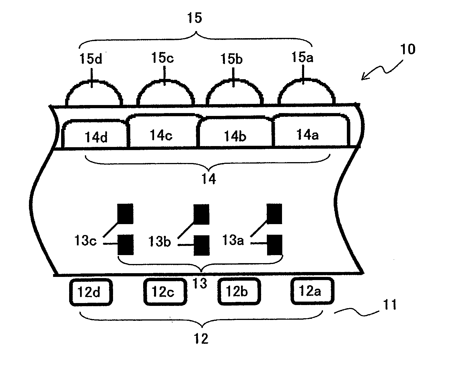
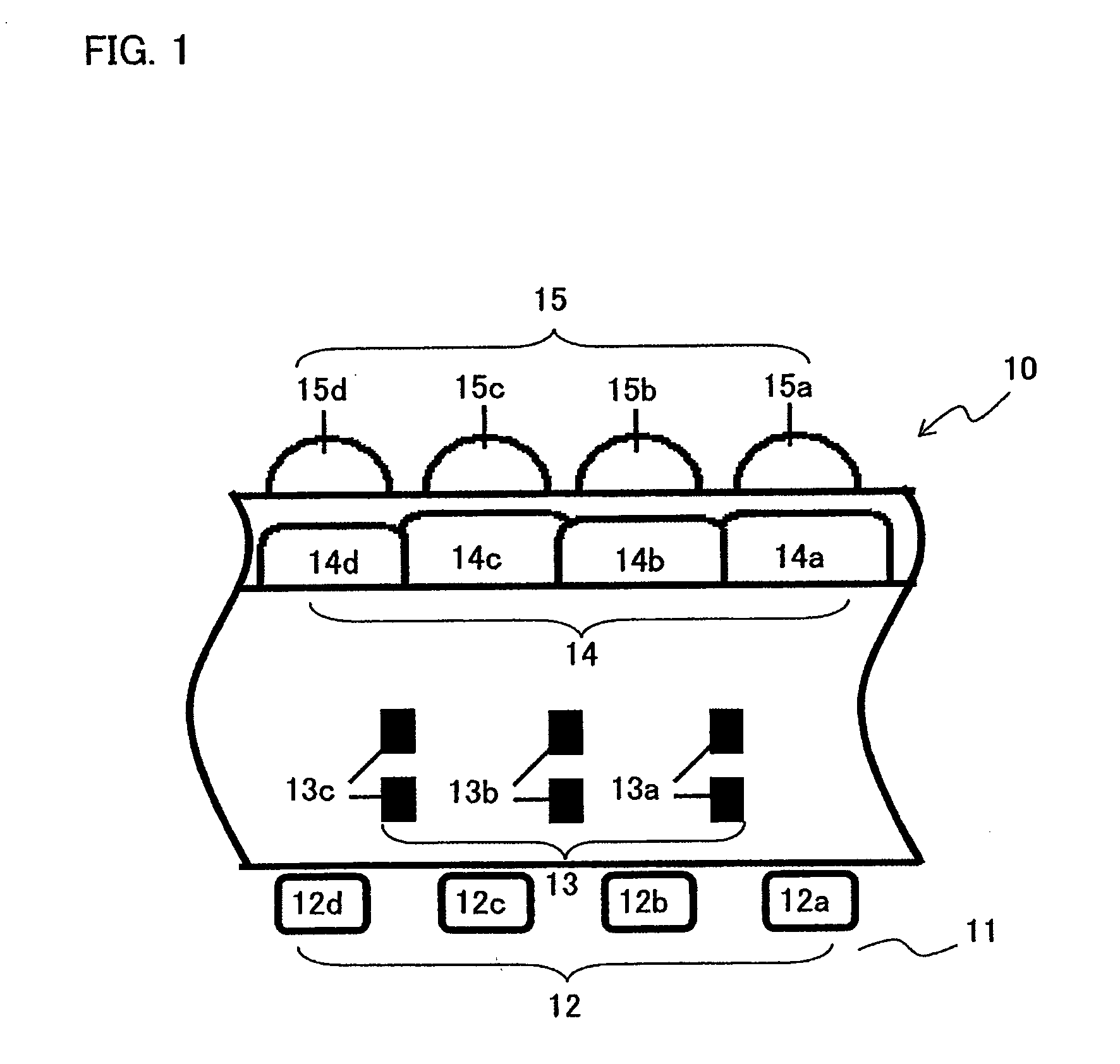
[0090]FIG. 1 is a longitudinal cross sectional view showing an exemplary essential structure of a solid-state image capturing device according to the embodiment of the present invention. Further, FIG. 1 also shows part of a light receiving region in the solid-state image capturing device according to the embodiment of the present invention.

[0091]In FIG. 1, a solid-state...


PUM


Abstract

A solid-state image capturing device is provided. In the solid-state image capturing device, at least any of openings of electrode wiring layers, color filters and microlenses are provided on a light incident side above light receiving elements as a light receiving region in which the plurality of light receiving elements are disposed on a semiconductor substrate or a semiconductor region provided on a substrate, wherein a shift amount of at least any of the openings of the electrode wiring layers, the color filters and the microlenses in relation to the light receiving elements or in relation to a standard position where a light flux is desired to pass through is calculated by Snell's law based on an incident angle θ0 of a light flux entering the light receiving region to a surface of the solid-state image capturing device.

Description

[0001]This Nonprovisional Application claims priority under 35 U.S.C. §119(a) on Patent Application No. 2007-128667 filed in Japan on May 14, 2007, the entire contents of which are hereby incorporated by reference.BACKGROUND OF THE INVENTION[0002]1. Field of the Invention[0003]The present invention relates to a solid-state image capturing device, such as a CCD image sensor and a CMOS image sensor, provided with at least any of openings of electrode wiring layers, color filters and microlenses above a plurality of light receiving elements as an image capturing region, for taking an image light from a subject by the plurality of light receiving elements; a solid-state image capturing apparatus provided with the solid-state image capturing device and an image capturing optical system in front of the solid-state image capturing device; and an electronic information device having, for example, a digital camera (e.g., digital video camera, digital still camera), an image input camera, a s...

Claims


Application Information

Patent Timeline
Patent Type & Authority Applications(United States)
IPC IPC(8): H01L31/0232H01L27/14H04N5/335H04N5/361H04N5/369
CPCH01L27/14627H01L27/14621H04N25/00
Inventor FUNAO, DAISUKE
Owner SHARP KK
Why Eureka
Try Eureka