

Locked phase active power current control circuit
a power current control circuit and active technology, applied in the direction of pulse automatic control, power conversion systems, instruments, etc., can solve the problems of affecting the effectiveness of feedback, difficulty in controlling and controlling, uneven brightness of background light, etc., to stabilize load and stable operation frequency of electronic switches
- Summary
- Abstract
- Description
- Claims
- Application Information
AI Technical Summary
Benefits of technology
Problems solved by technology
Method used
Image

Examples
first embodiment
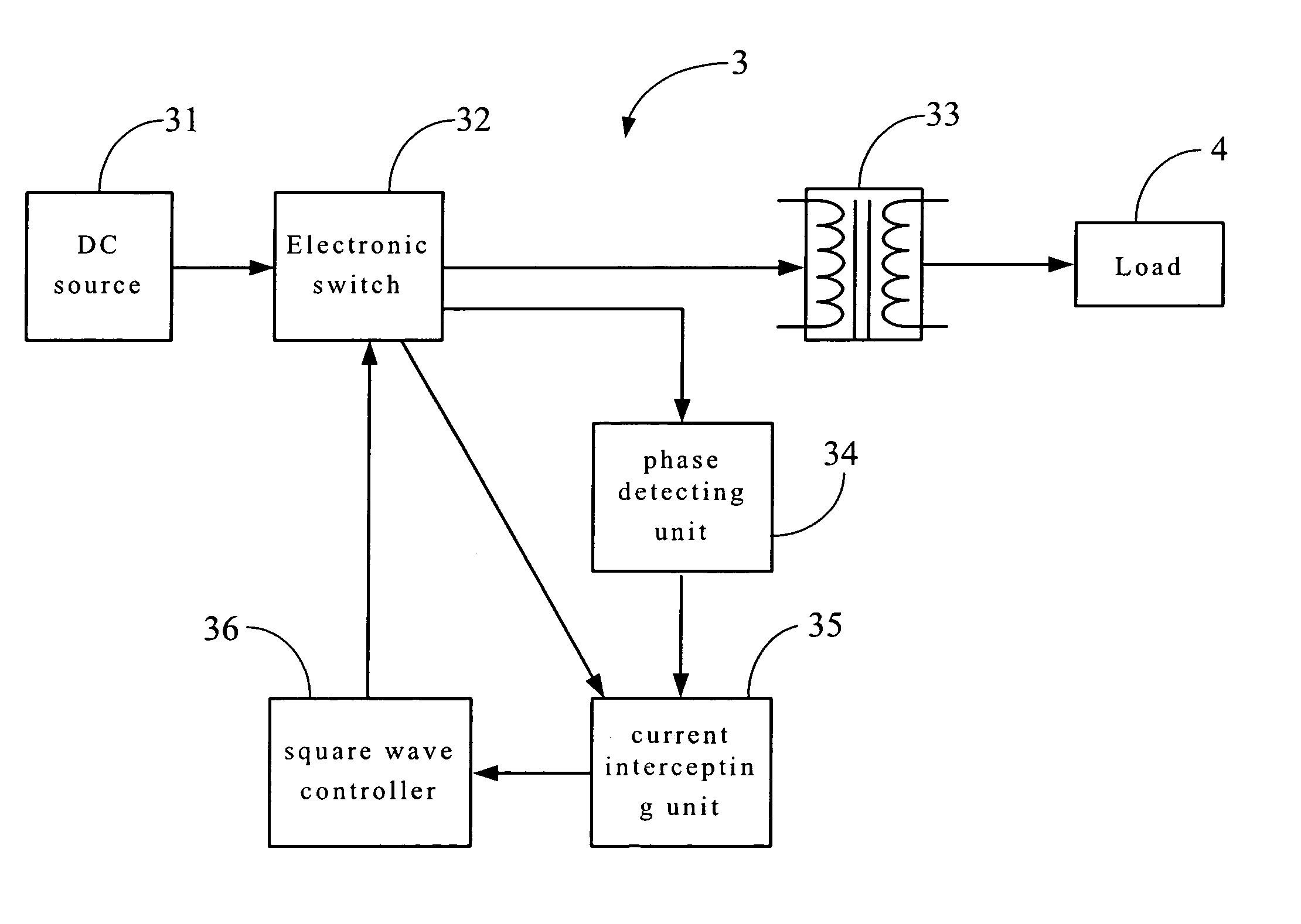
[0026]FIG. 4A is an operational flow chart in the present invention, wherein the locked phase active power current control circuit 3 comprises the following elements and functions:
[0027]A DC source 31 outputs a DC signal to an electronic switch 32.
[0028]The electronic switch 32 receives the DC signal outputted from the DC source 31 and converts it to a square wave signal and outputs the square wave signal to a driving transformer 33 and a phase detecting unit 34.
[0029]The driving transformer 33 receives the square wave signal outputted from the electronic switch 32 and supplies it to a load 4 after boosting up the voltage.
[0030]A phase detecting unit 34, which receives the square wave signal outputted from the electronic switch 32, detects a phase signal of the square wave and outputs the detected phase signal to a current intercepting unit 35.
[0031]The current intercepting unit 35 receives the detected phase signal outputted from the phase detecting unit 34, compares it with a curr...
second embodiment
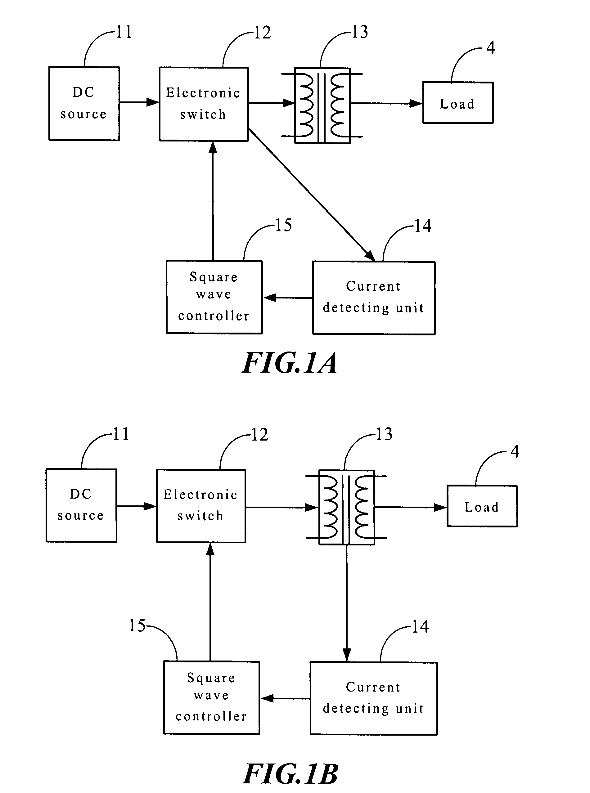
[0033]FIG. 4B is an operational flow chart in the present invention, wherein the locked phase active power current control circuit 3 comprises the following elements and functions:
[0034]A DC source 31 provides a DC signal to an electronic switch 32.
[0035]The electronic switch 32 receives the DC signal outputted from the DC source 31 and converts it to a square wave signal and outputs the square wave signal to a driving transformer 33 and a phase detecting unit 34.
[0036]The driving transformer 33 receives the square wave signal outputted from the electronic switch 32 and supplies it to a load 4 after boosting up the voltage.
[0037]A phase detecting unit 34, which receives the square wave signal outputted from the electronic switch 32, detects a phase signal of the square wave and outputs the detected phase signal to a current intercepting unit 35.
[0038]The current intercepting unit 35 receives the detected phase signal outputted from the phase detecting unit 34 and compares it with a ...
third embodiment
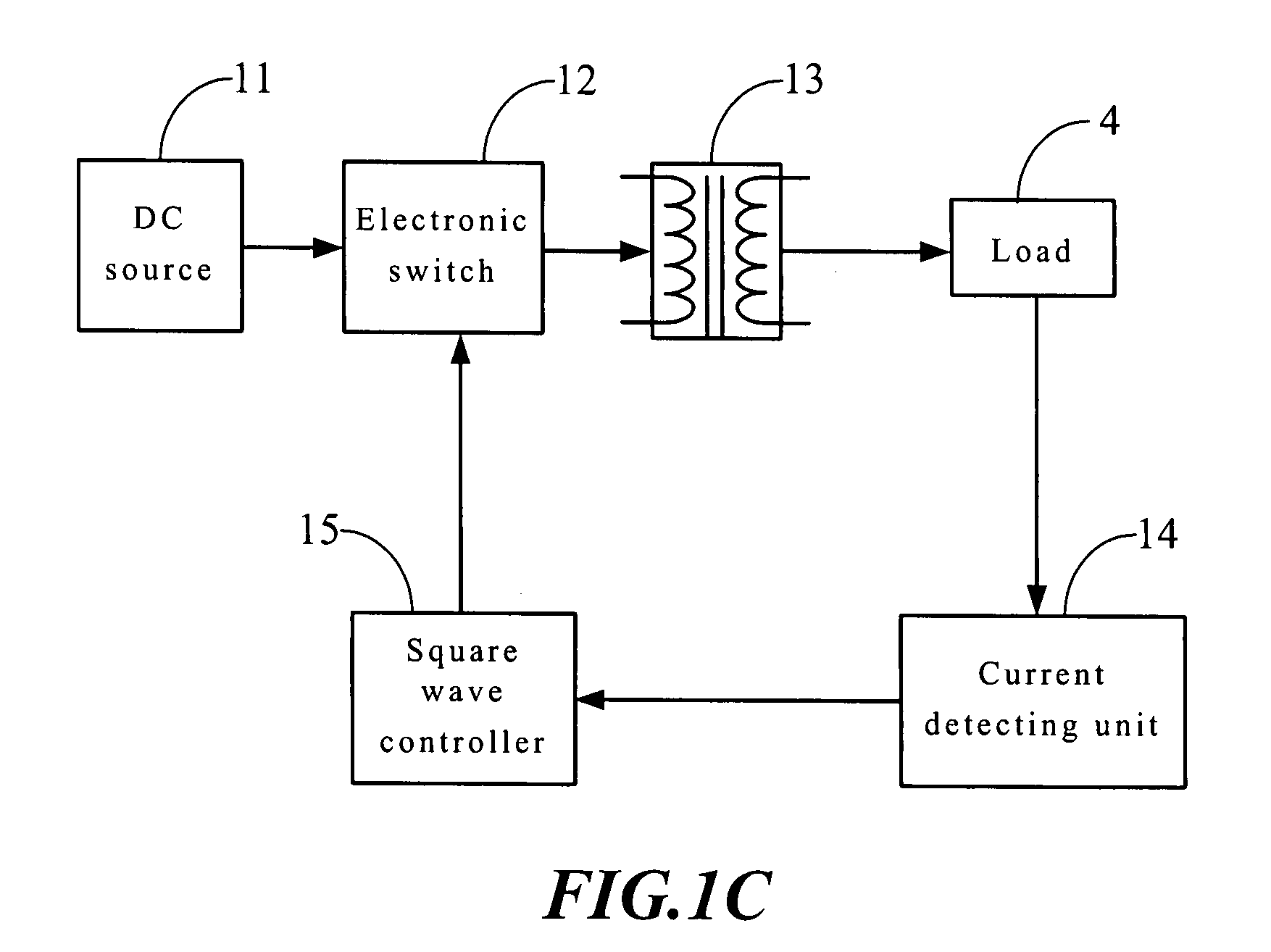
[0040]FIG. 4C is an operational flow chart in the present invention, wherein the locked phase active current control circuit 3 comprises the following elements and functions:
[0041]A DC source 31 provides a DC signal to an electronic switch 32.
[0042]The electronic switch 32 receives the DC signal outputted from the DC source 31 and converts it to a square wave signal and outputs the square wave signal to a driving transformer 33 and a phase detecting unit 34.
[0043]The driving transformer 33 receives the square wave signal outputted from the electronic switch 32 and supplies it to a load 4 after boosting up the voltage.
[0044]A phase detecting unit 34, which receives the square wave signal outputted from the electronic switch 32, detects a phase signal of the square wave and outputs the detected phase signal to a current intercepting unit 35.
[0045]The current intercepting unit 35 receives the detected phase signal outputted from the phase detecting unit 34 and compares it with a curren...
PUM
 Abstract
Description
Claims
Application Information