Check patentability & draft patents in minutes with Patsnap Eureka AI!

Antenna Design For FM Radio Receivers

Active Publication Date: 2009-03-26
IBIQUITY DIGITAL CORP
View PDF13 Cites 54 Cited by
  • Summary
  • Abstract
  • Description
  • Claims
  • Application Information

AI Technical Summary

Benefits of technology

[0010]In a second aspect, the invention provides a method for receiving a radio signal. The method includes the steps of: receiving the radio signal on at least one of a first antenna and a second antenna, calculating a first quality metric for the received radio signal, calculating a second quality metric for the received radio signal, selecting the first antenna, the second antenna or a combination of the first and second antennas to receive the radio signal, based on the first and second quality metrics, and tuning an impedance of the selected antenna to match the impedance of a receiver.
[0011]In a third aspect, the invention provides an apparatus for receiving a radio signal. The apparatus includes a first antenna, a second antenna, a processor for calculating a first quality metric for the received ra

Problems solved by technology

However, existing FM analog portable and hand-held radio receiver devices typically have very poor reception.
These devices present several challenges, including small size and weight, EMI caused by antenna proximity to electronics, variability due to the effects of the human body, and the need to support indoor reception.
An earbud dipole antenna solution yields poor performance due to the limited distance between the ears for the upper and lower elements of the antenna, whereas a monopole earbud antenna solution requires the addition of a ground plane to replace the lower-half element of a dipole.
However, today's hand-held devices are typically much smaller.
The quality of reception for both monopole and dipole earbud antennas is variable and unpredictable, depending significantly on the orientation of the user and the antenna elements.
Moreover, EMI between the antenna and nearby electronic elements such as the power supply can contribute to loss in performance.
In addition, these antennas have unbalanced impedance.
This solution is undesirable, however, because the antenna element is not portable and cannot travel with the user.

Method used


Image

  • Antenna Design For FM Radio Receivers
  • Antenna Design For FM Radio Receivers
  • Antenna Design For FM Radio Receivers

Examples


Embodiment Construction

[0045]FIGS. 1-11 and the accompanying description herein provide a general description of an IBOC system, including broadcasting equipment structure and operation, receiver structure and operation, and the structure of IBOC DAB waveforms. FIGS. 12-16 and 29 and the accompanying description herein provide a detailed description of antenna designs according to aspects of the present invention. FIGS. 17-28 and the accompanying description herein provide a detailed description of the structure and operation of antenna element diversity and adaptive impedance matching algorithms according to aspects of the present invention.

IBOC System and Waveforms

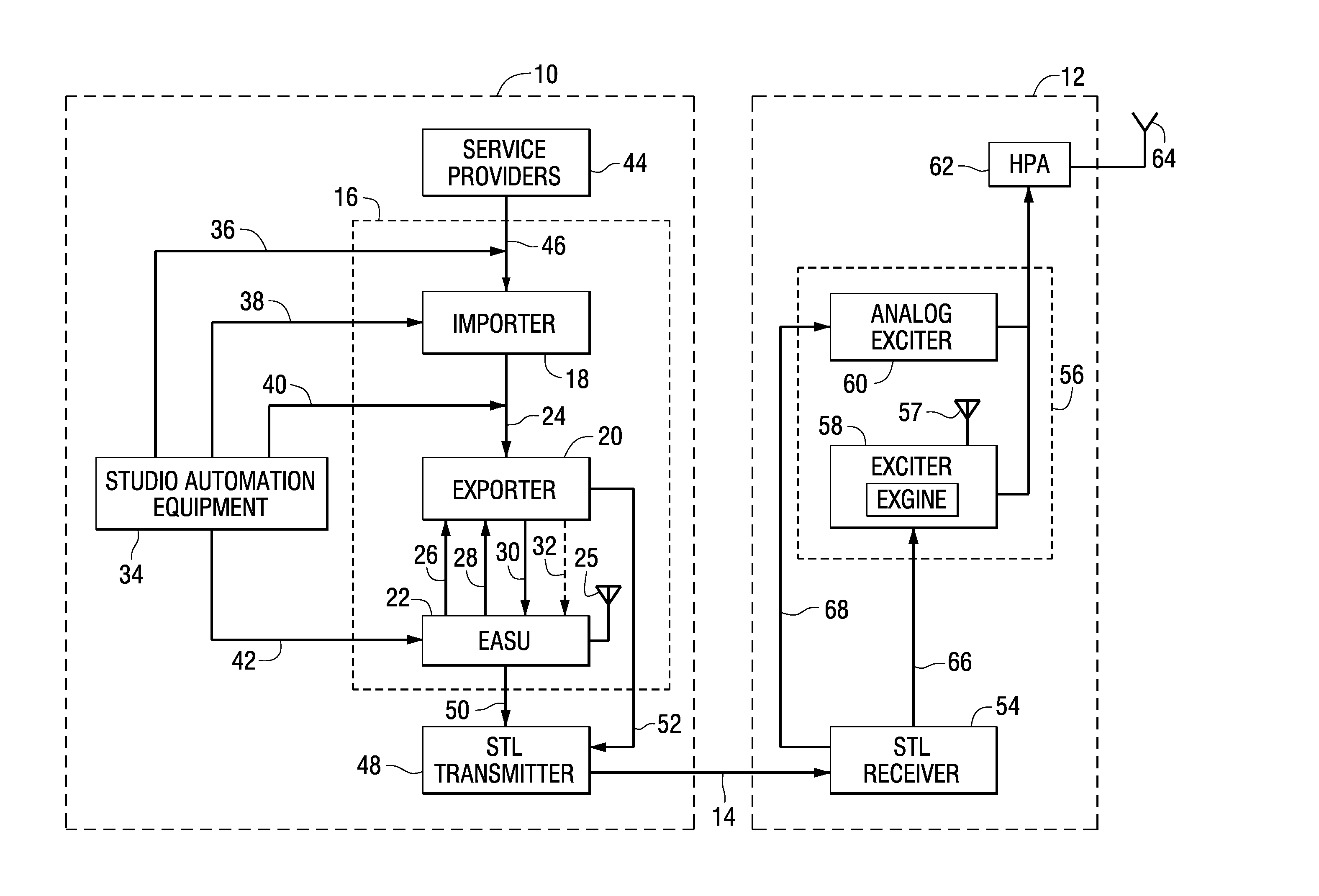
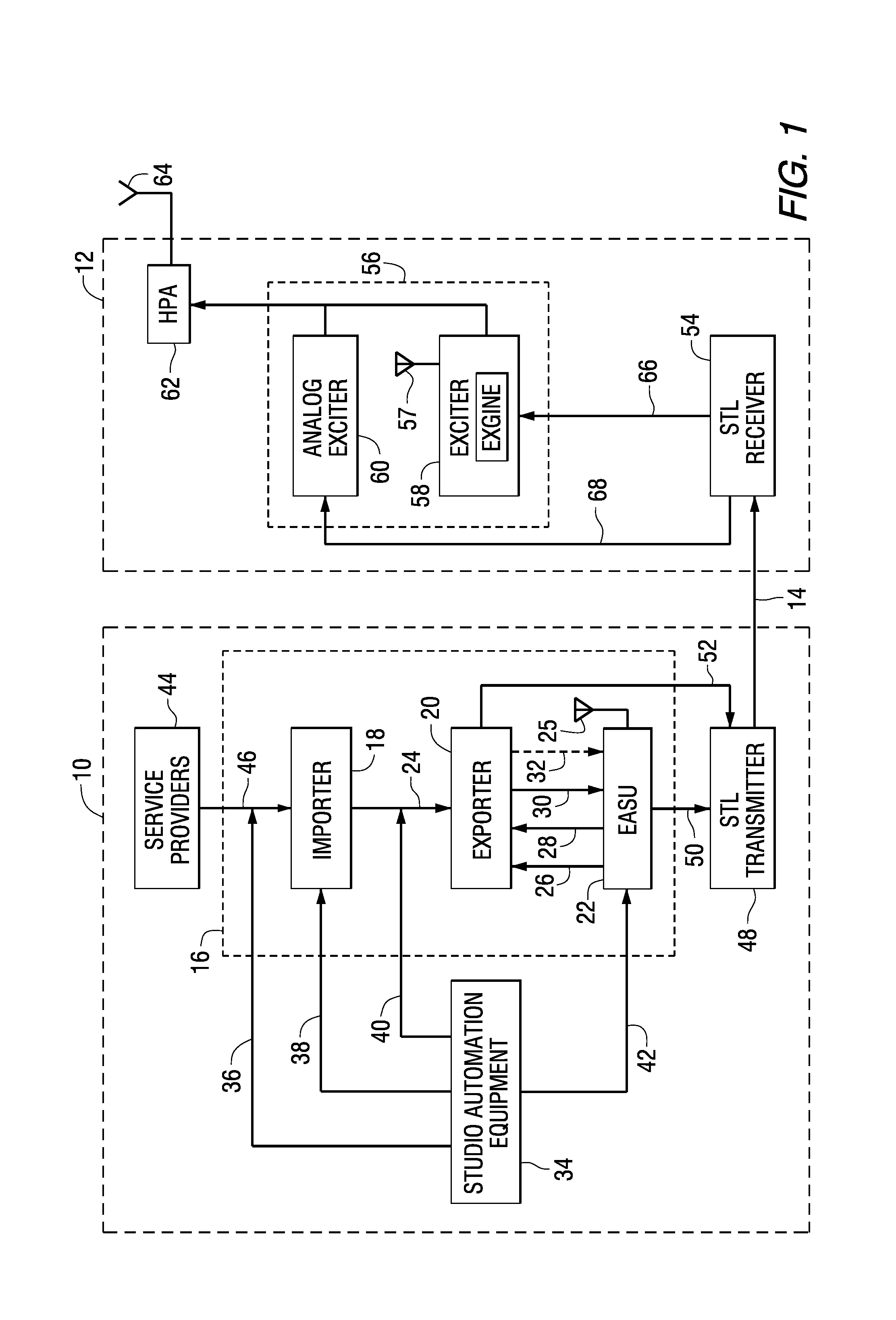
[0046]Referring to the drawings, FIG. 1 is a functional block diagram of the relevant components of a studio site 10, an FM transmitter site 12, and a studio transmitter link (STL) 14 that can be used to broadcast an FM IBOC DAB signal. The studio site includes, among other things, studio automation equipment 34, an Ensemble Operations Center ...


PUM


Abstract

An apparatus includes first and second speakers, and an antenna including a first pair of wires connected to the first speaker, a second pair of wires connected to the second speaker, and a conductive sleeve surrounding portions of the first and second pairs of wires, the sleeve forming a coaxial capacitor with the first and second pairs of wires. The apparatus can further include an inductor connected between the first and second pairs of wires and the sleeve, to form a resonant circuit with the coaxial capacitor.

Description

FIELD OF THE INVENTION[0001]This invention relates to an antenna for receiving FM analog and digital radio broadcast signals, and more particularly to methods and apparatus for implementing in a portable digital radio receiver an antenna for receiving a digital radio broadcast signal.BACKGROUND OF THE INVENTION[0002]Digital radio broadcasting technology delivers digital audio and data services to mobile, portable, and fixed receivers. One type of digital radio broadcasting, referred to as in-band on-channel (IBOC) digital audio broadcasting (DAB), uses terrestrial transmitters in the existing Medium Frequency (MF) and Very High Frequency (VHF) radio bands. HD Radio™ technology, developed by iBiquity Digital Corporation, is one example of an IBOC implementation for digital radio broadcasting and reception. IBOC DAB signals can be transmitted in a hybrid format including an analog modulated carrier in combination with a plurality of digitally modulated carriers or in an all-digital fo...

Claims


Application Information

Patent Timeline
IPC IPC(8): H01Q1/50
CPCH01Q1/273H04B17/309H04B7/0805H01Q1/46
Inventor PEYLA, PAUL J.KROEGER, BRIAN WILLIAM
Owner IBIQUITY DIGITAL CORP
Features
  • R&D
  • Intellectual Property
  • Life Sciences
  • Materials
  • Tech Scout
  • Unparalleled Data Quality
  • Higher Quality Content
  • 60% Fewer Hallucinations
Learn More