Eureka AIR delivers breakthrough ideas for toughest innovation challenges, trusted by R&D personnel around the world.

Load sensing forced mode lock

a force mode and mode lock technology, applied in the field of hardware graphics systems, can solve the problems of inability inability to consistently reliable time out method, and inability to provide software-based functionality (e.g. operating systems) of the system to provide even a time out mechanism, so as to restore output settings and usability of display devices. , the effect of restoring the output to settings

Inactive Publication Date: 2009-03-26
NVIDIA CORP
View PDF18 Cites 10 Cited by
  • Summary
  • Abstract
  • Description
  • Claims
  • Application Information

AI Technical Summary

Benefits of technology

The present invention provides a solution for users to reliably restore the output of a display device to its original settings. This is achieved by detecting changes in the output connector and automatically adjusting the output settings to a compatible mode. Additionally, a control panel application is provided for users to change the output settings. The invention also includes a system for outputting graphics with multiple display devices, and a method for restoring visual output on a display device. These technical effects provide users with a transparent and intuitive way to restore the output of a display device.

Problems solved by technology

A problem exists however when the user sets output settings (e.g., resolution or refresh rate) beyond the capabilities of a display device.
Upon pressing the remote control button to select the high-resolution, the user will then be presented with either a blank screen or a corrupted and incomprehensible video signal because the display device is not capable of displaying the output.
Unfortunately, this time out method is not consistently reliable, because depending upon how it is implemented (e.g., set-top box, media center PC, etc.), the timeout function may freeze or stop functioning.
With respect to PC-based systems (e.g., small form factor set-top box PC systems, wired or wirelessly connected PCs, etc.), the software-based functionality (e.g. operating systems) of the systems may not provide even a time out mechanism.
In this case, the user will be stuck with the unsupported resolution.
Being suddenly confronted with a blank screen, the user may also not realize what the mistake was and further be stuck because he / she does not know how to go about fixing the problem.
Unfortunately, the output settings may exceed the capabilities of the newly attached display device and the user remains stuck with incomprehensible display device output.

Method used


Image

  • Load sensing forced mode lock
  • Load sensing forced mode lock
  • Load sensing forced mode lock

Examples


Embodiment Construction

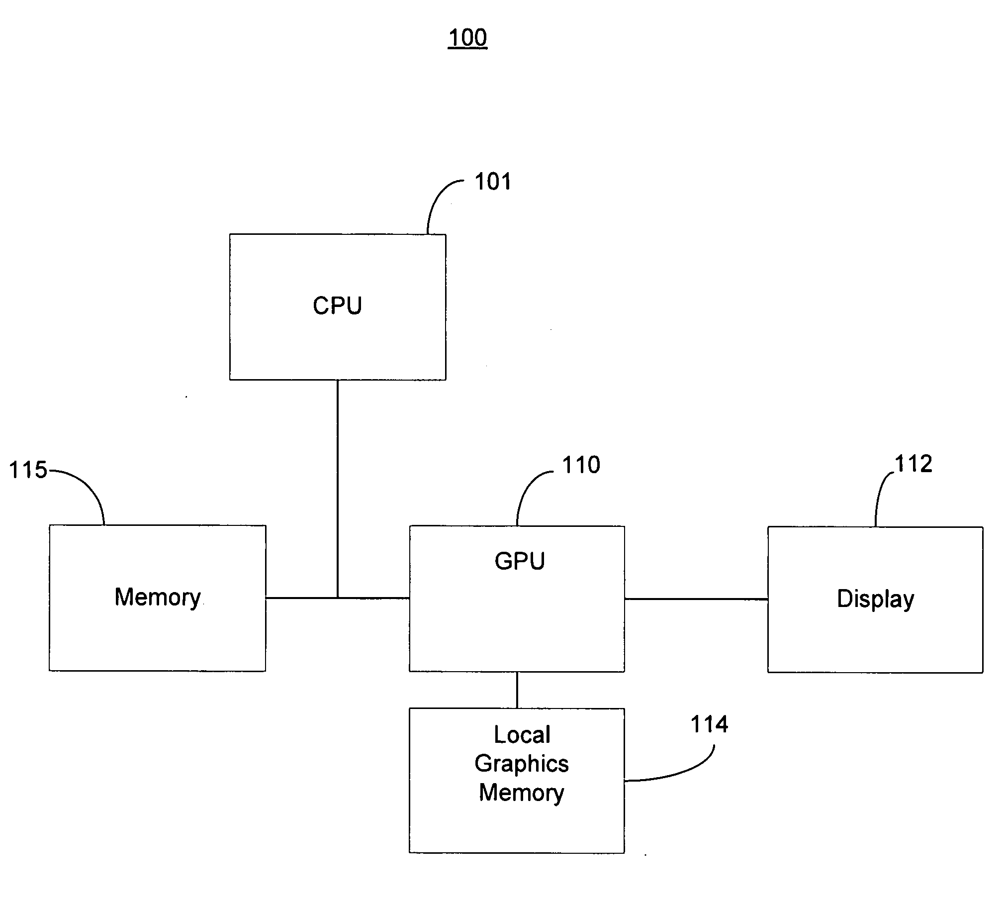
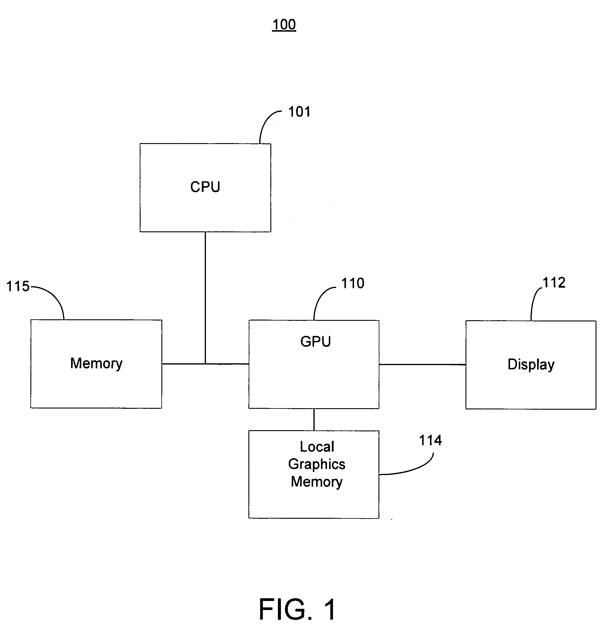
[0022]Reference will now be made in detail to the preferred embodiments of the present invention, examples of which are illustrated in the accompanying drawings. While the invention will be described in conjunction with the preferred embodiments, it will be understood that they are not intended to limit the invention to these embodiments. On the contrary, the invention is intended to cover alternatives, modifications and equivalents, which may be included within the spirit and scope of the invention as defined by the appended claims. Furthermore, in the following detailed description of embodiments of the present invention, numerous specific details are set forth in order to provide a thorough understanding of the present invention. However, it will be recognized by one of ordinary skill in the art that the present invention may be practiced without these specific details. In other instances, well-known methods, procedures, components, and circuits have not been described in detail ...


PUM


Abstract

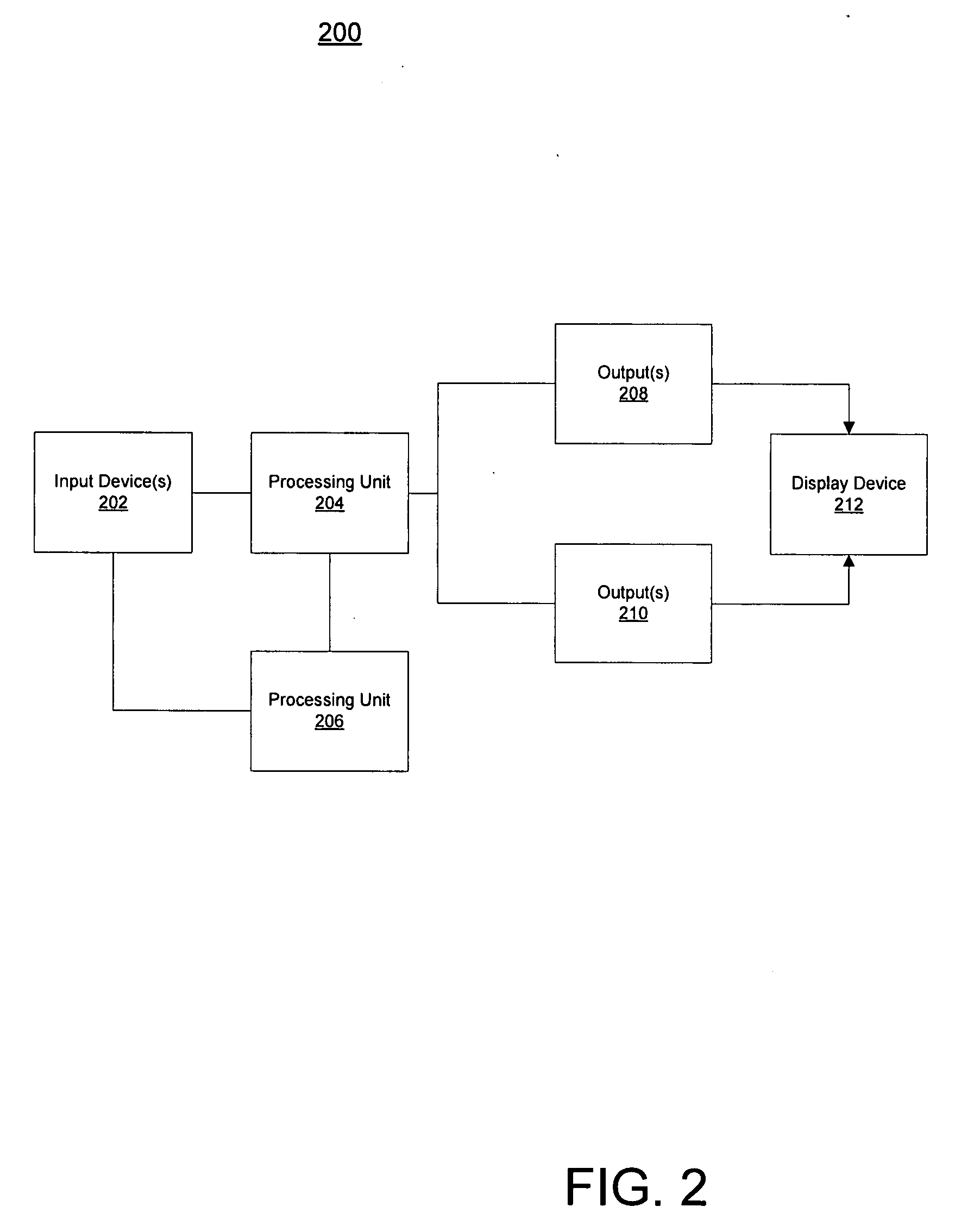
A method for restoring visual output to a display device. The method includes detecting a display device connection change on an output connector and changing output settings to a compatible output mode on the output connector. The method further includes cloning graphics output to the output connector. The graphics output is modified for display on the second output connector. Subsequently, a control panel application is executed to present an on-display control for changing the output mode of the first output connector.

Description

CROSS REFERENCE TO RELATED APPLICATION[0001]This application is related to commonly assigned U.S. patent application Ser. No. ______, entitled “OUTPUT RESTORATION WITH INPUT SELECTION” by Herz et al., attorney docket number NVID-P003483, which is incorporated herein in its entirety.FIELD OF THE INVENTION[0002]The present invention is generally related to hardware graphics systems.BACKGROUND OF THE INVENTION[0003]Increasing distribution of digital content has helped the growth of more advanced display technologies such as high definition televisions. At the same time computers have developed an increasing role in entertainment systems and thus are connected with high definition devices such as televisions. In order to get the best possible visual experience, the output settings need to match content format and the capabilities of the display device. Therefore, there are times when a user will need to change the resolution of the output or when a new device is connected.[0004]A proble...

Claims


Application Information

Patent Timeline
Patent Type & Authority Applications(United States)
IPC IPC(8): G09G3/36
CPCG06F3/14G06F3/1423G09G2370/042G09G2340/0407G09G2360/02G09G5/006
Inventor HERZ, WILLIAMS S.HAN, GANG
Owner NVIDIA CORP
Why Eureka
Eureka Blog
Learn More