Magnetic head and magnetic recording device

Active Publication Date: 2009-03-26
KK TOSHIBA
View PDF96 Cites 120 Cited by
  • Summary
  • Abstract
  • Description
  • Claims
  • Application Information

AI Technical Summary

Benefits of technology

[0012]The present invention has been made in view of these circumstances, and an object thereof is to provide a magnetic head that can generate

Problems solved by technology

This leads to a decrease in reproduction outputs, and hinders stable recording.
If an actual recording operation is performed, the operations of the spin torque oscillators become unstable due to the magn

Method used


Image

  • Magnetic head and magnetic recording device
  • Magnetic head and magnetic recording device
  • Magnetic head and magnetic recording device

Examples


first embodiment

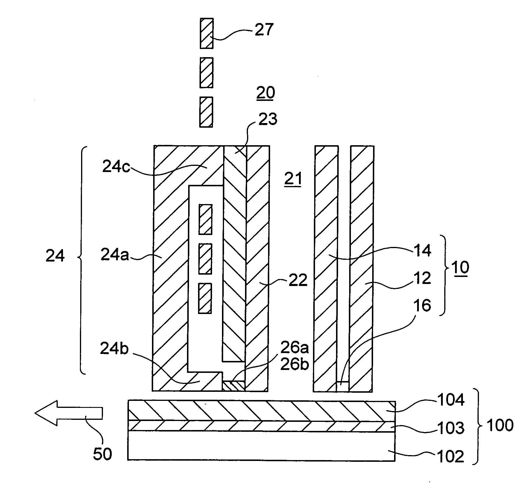
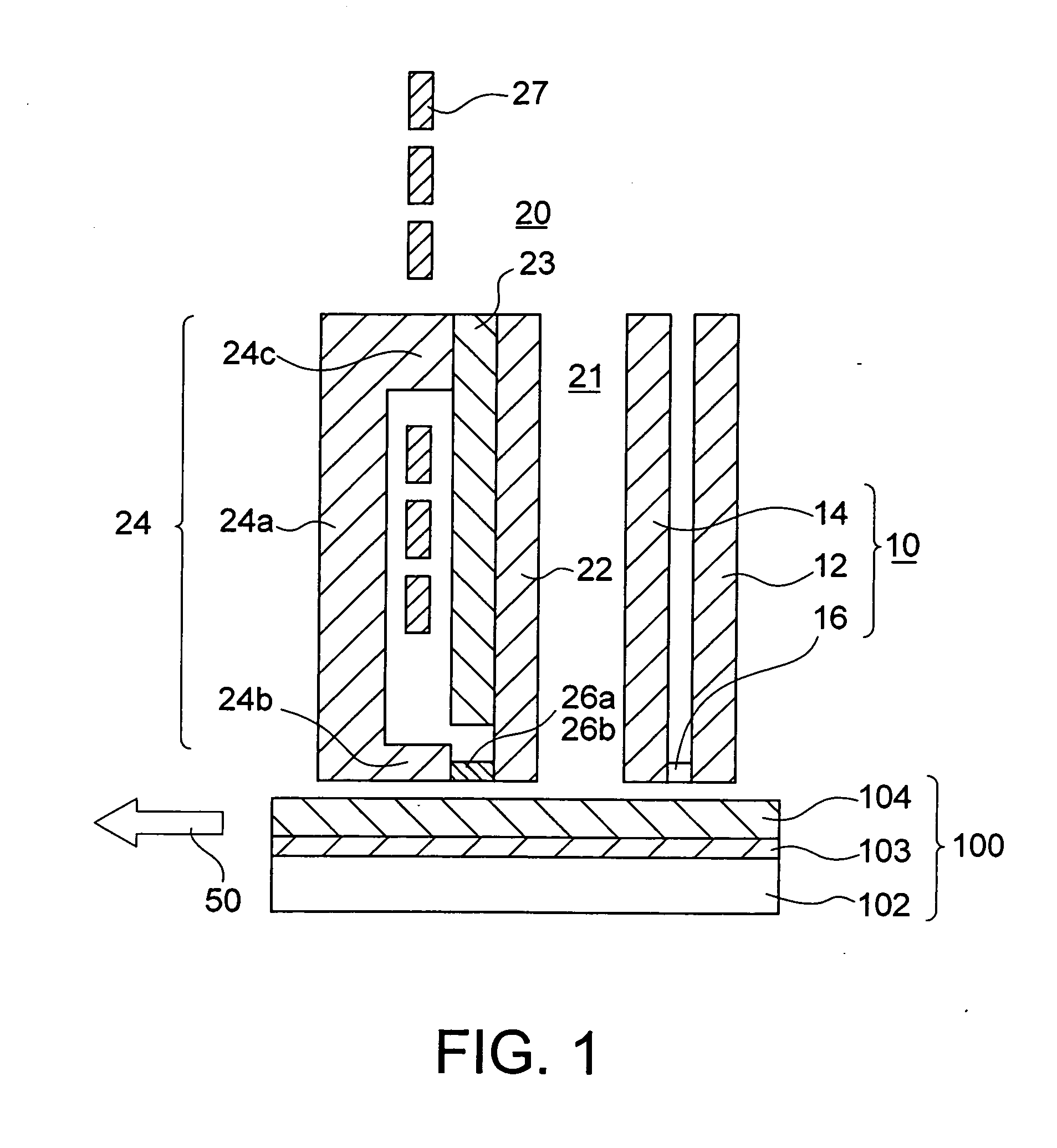
[0033]FIGS. 1 and 2 illustrate a magnetic head in accordance with a first embodiment of the present invention. FIG. 1 is a cross-sectional view of the magnetic head of this embodiment, taken along a plane that is perpendicular to the medium facing plane and extends in a direction (the track longitudinal direction) parallel to the moving direction of the magnetic recording medium. FIG. 2 is a plan view of the magnetic head of this embodiment, seen from the magnetic recording medium side.

[0034]The magnetic head of this embodiment includes a reproducing head unit 10 and a writing head unit 20. The reproducing head unit 10 includes a magnetic shield 12, a magnetic shield 14, and a magnetic reproducing element 16 interposed between the magnetic shield 12 and the magnetic shield 14. The magnetic reproducing element 16 may be a GMR (Giant Magneto-Resistive effect) element or a TMR (Tunneling Magneto-Resistive effect) element. The magnetic reproducing element 16 is located between the end p...

second embodiment

[0044]FIGS. 5 and 6 illustrate a magnetic head in accordance with a second embodiment of the present invention. FIG. 5 is a cross-sectional view of the magnetic head of this embodiment, taken along a plane that is perpendicular to the medium facing plane and extends in a direction (the track longitudinal direction) parallel to the moving direction of the magnetic recording medium. FIG. 6 is a plan view of the magnetic head of this embodiment, seen from the magnetic recording medium side.

[0045]The magnetic head of this embodiment is the same as the magnetic head of the first embodiment shown in FIGS. 1 and 2, except that the writing head unit 20 is replaced with a writing head unit 20A. As shown in FIGS. 5 and 6, the writing head unit 20A differs from the writing head unit 20 of the first embodiment in that the spin torque oscillators 26a and 26b are provided on the two sides of the main magnetic pole (the recording magnetic pole) 22. The spin torque oscillators 26a and 26b are locat...

third embodiment

[0049]FIGS. 7 and 8 illustrate a magnetic head in accordance with a third embodiment of the present invention. FIG. 7 is a cross-sectional view of the magnetic head of this embodiment, taken along a plane that is perpendicular to the medium facing plane and extends in a direction (the track longitudinal direction) parallel to the moving direction of the magnetic recording medium. FIG. 8 is a plan view of the magnetic head of this embodiment, seen from the magnetic recording medium side.

[0050]The magnetic head of this embodiment is the same as the magnetic head of the first embodiment shown in FIGS. 1 and 2, except that the writing head unit 20 is replaced with a writing head unit 20B. This writing head unit 20B has a magnetic core 21A that is the same as the magnetic core 21, except that the write shield 24b of the return yoke 24 is removed. The spin torque oscillators 26a and 26b are provided on the leading side and the trailing side of the main magnetic pole 22, respectively. In F...


PUM


Abstract

It is made possible to provide a magnetic head that generates a sufficient high-frequency magnetic field for assisting recording operations, and a magnetic recording device that includes the magnetic head. A magnetic head includes: a recording magnetic pole; a return yoke magnetically coupled to the recording magnetic pole; and at least two spin torque oscillators provided near the recording magnetic pole.

Description

CROSS-REFERENCE TO RELATED APPLICATION[0001]This application is based upon and claims the benefit of priority from prior Japanese Patent Application No. 2007-247169 filed on Sep. 25, 2007 in Japan, the entire contents of which are incorporated herein by reference.BACKGROUND OF THE INVENTION[0002]1. Field of the Invention[0003]The present invention relates to a magnetic head that records signals on a magnetic recording medium, and a magnetic recording device.[0004]2. Related Art[0005]In recent years, magnetic recording devices such as hard disk devices have been rapidly becoming smaller and having higher densities, and this trend is expected to continue in the future. To achieve higher density in magnetic recording, it is necessary to narrow the recording track width to increase the recording track density. It is also necessary to increase the recording density in the longitudinal direction of the track, which is the line recording density.[0006]However, as the recording density beco...

Claims


Application Information

Patent Timeline
IPC IPC(8): G11B5/33
CPCG11B5/02G11B5/1278G11B2005/0024G11B2005/0005G11B5/314
Inventor FUNAYAMA, TOMOMIYAMADA, KENICHIROTAKAGISHI, MASAYUKITAKASHITA, MASAHIROSHIMIZU, MARIKOAKIYAMA, JUNICHIIWASAKI, HITOSHI
Owner KK TOSHIBA
Why Eureka
Try Eureka