Systems and methods for flow mirroring with network-scoped connection-oriented sink

a network-scoped connection and sink technology, applied in the field of packet network, can solve the problems of inability to sink mirrored data to a port, needlessly mirroring all traffic on the port, etc., and achieve the effect of reducing bandwidth requirements for network-scoped connection-oriented sinks

Active Publication Date: 2009-03-26
CIENA
View PDF6 Cites 36 Cited by
  • Summary
  • Abstract
  • Description
  • Claims
  • Application Information

AI Technical Summary

Benefits of technology

[0008]In various exemplary embodiments, the present invention provides systems and methods for sinking one or more flows as port mirrored data to any node in a network through a network-scoped connection-oriented sink. Moreover, the network, itself, is configured to convey the mirrored data to the sink, without the need for any facilities expressly dedicated for this purpose. The present invention removes the requirement to co-locate the sink port within the same logical node as the mirrored port. Additionally, the present invention only mirrors a specific flow from a port, reducing bandwidth requirements for the network-scoped connection-oriented sink. The present invention uses a mirrored flow configured as a provisioned layer two point-to-point connection, such as a Switched Permanent Virtual Circuit (SPVC), Pseudo-Wire (PWE3, i.e. a Multi-Protocol Label Switching (MPLS)-equivalent to the SPVC), a Virtual Local Area Network (VLAN) cross-connect, Provider Backbone Bridging—Traffic Engineering (PBB-TE), and the like.

Problems solved by technology

Disadvantageously, the inability to sink the mirrored data to a port on any arbitrary node in the network is a serious shortcoming.
Disadvantageously, this leads to needlessly mirroring all traffic on the port, and requiring the specific flow to be access at the mirror sink.

Method used


Image

  • Systems and methods for flow mirroring with network-scoped connection-oriented sink
  • Systems and methods for flow mirroring with network-scoped connection-oriented sink
  • Systems and methods for flow mirroring with network-scoped connection-oriented sink

Examples


Embodiment Construction

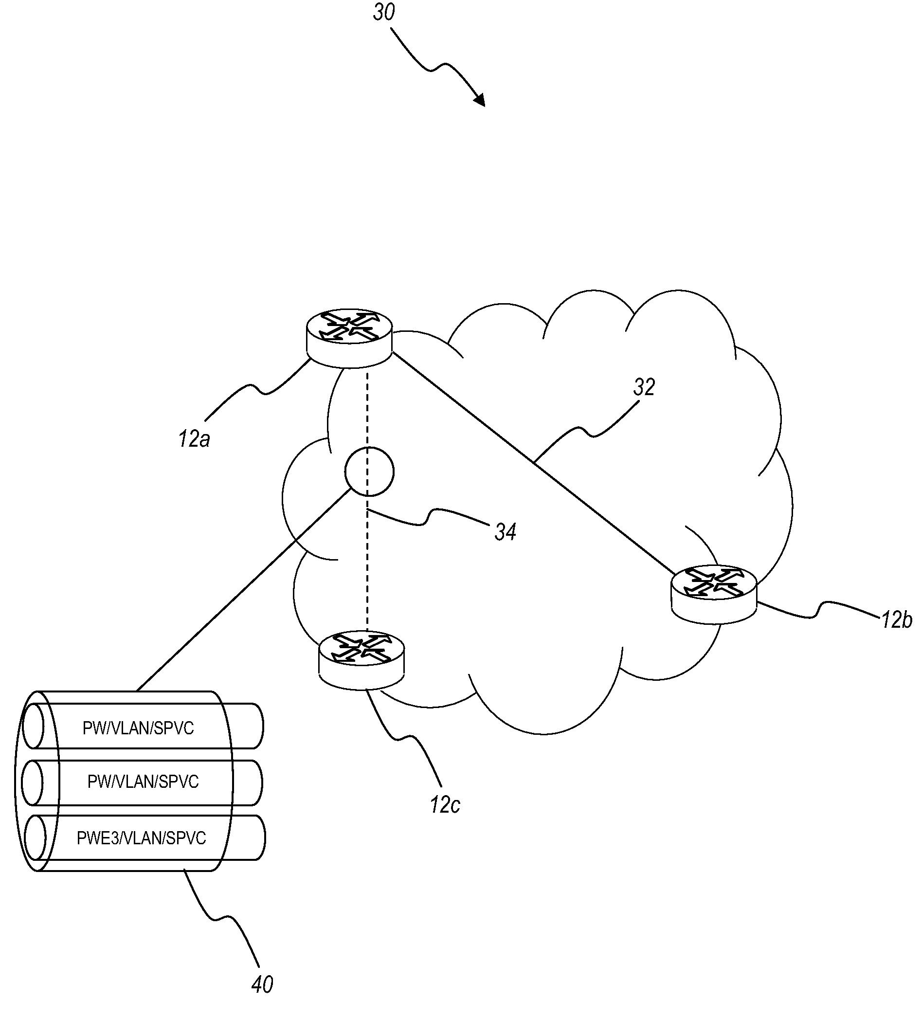
[0021]In various exemplary embodiments, the present invention provides systems and methods for sinking one or more flows as port mirrored data to any node in a network through a network-scoped connection-oriented sink. Moreover, the network, itself, is configured to convey the mirrored data to the sink, without the need for any facilities expressly dedicated for this purpose. The present invention removes the requirement to co-locate the sink port within the same logical node as the mirrored port.

[0022]The present invention uses a mirrored flow configured as a provisioned layer two point-to-point connection, such as a Switched Permanent Virtual Circuit (SPVC), Pseudo-Wire (PWE3, i.e. a Multi-Protocol Label Switching (MPLS)-equivalent to the SPVC), a Virtual Local Area Network (VLAN) cross-connect, Provider Backbone Bridging—Traffic Engineering (PBB-TE), and the like. The provisioned point-to-point connection is configured between the mirrored port to a sink port. The node with the m...


PUM


Abstract

Systems and methods for sinking port mirrored from one or more identified flows of data to any node in a network are provided. Moreover, the network is configured to convey the mirrored data to the sink, without the need for any facilities expressly dedicated for this purpose. The present invention removes the requirement to co-locate the sink port within the same logical node. The present invention uses a mirrored flow configured as a provisioned layer two point-to-point connection, such as a Switched Permanent Virtual Circuit (SPVC), Pseudo-Wire (PWE3), a Virtual Local Area Network (VLAN) cross-connect, Provider Backbone Bridging—Traffic Engineering (PBB-TE), and the like. The node with the mirrored port is configured to create copies of the appropriate set of packets (i.e., ingress, egress packets, or both based on provisioning and based on the identified flow), and to forward the packets to the sink port through the provisioned point-to-point connection.

Description

CROSS-REFERENCE TO RELATED APPLICATION(S)[0001]This application is a continuation-in-part of co-pending U.S. patent application Ser. No. 11 / 859,973 filed Sep. 24, 2007, and entitled “SYSTEMS AND METHODS FOR PORT MIRRORING WITH NETWORK-SCOPED CONNECTION-ORIENTED SINK,” the contents of which are incorporated in full by reference herein.FIELD OF THE INVENTION[0002]The present invention relates generally to packet networks, and more particularly, the present invention provides systems and methods for sinking port mirrored data from one or more particularly identified flows to any node in a network. Moreover, the network, itself, is configured to convey the mirrored flows to the sink, without the need for any facilities expressly dedicated for this purpose.BACKGROUND OF THE INVENTION[0003]Port mirroring, also known as a roving analysis port, port monitoring, switched port analyzer, and the like, is a method of monitoring network traffic. For example, a switch or the like is configured to...

Claims


Application Information

Patent Timeline
Patent Type & Authority Applications(United States)
IPC IPC(8): G06F11/00
CPCH04L12/24H04L12/2697H04L43/50H04L43/18H04L41/00
Inventor PARKER, RONALD MARKLEDUC, CHRISTOPHER MICHAELGHODRAT, MORTEZA
Owner CIENA
Why Eureka
Try Eureka