Speaker

a speaker and speaker technology, applied in the field of speakers, can solve the problems of reducing driving efficiency and heavy weight of speaker excursion parts, and achieve the effect of improving driving efficiency

Active Publication Date: 2009-03-26
PANASONIC CORP
View PDF4 Cites 2 Cited by
  • Summary
  • Abstract
  • Description
  • Claims
  • Application Information

AI Technical Summary

Benefits of technology

[0016]The structure discussed above allows suppressing the distortion, and the lighter excursion parts weight of this structure invites an improvement in the driving efficiency.

Problems solved by technology

The foregoing conventional speaker, however, employs suspension holder 6A which firmly holds diaphragm 3A, so that the weight of the speaker excursion parts becomes heavy.
The heavy weight does not matter to a woofer to which a large amount of output is applied, but it matters to a full-range and a mid-range speaker because the heavy excursion parts weight lowers the driving efficiency.

Method used


Image

  • Speaker
  • Speaker
  • Speaker

Examples


exemplary embodiment 1

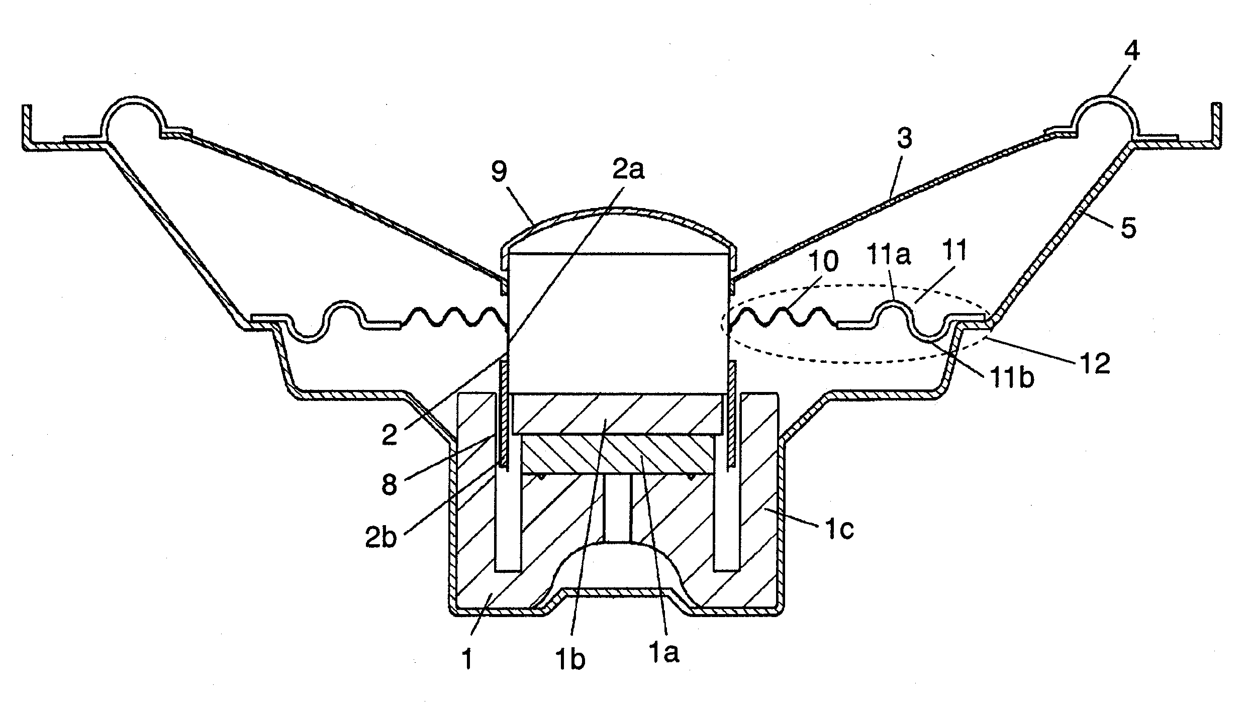
[0031]The first exemplary embodiment is demonstrated hereinafter with reference to the accompanying drawings. FIG. 1 shows a sectional view of a speaker in accordance with the first embodiment of the present invention.

[0032]Cone-shaped frame 5 includes magnetic circuit 1 at its bottom center, and magnetic circuit 1 is formed by combining and bonding disk-shaped magnet 1a, disk-shaped plate 1b, and cylindrical yoke 1c together. Inner wall of yoke 1c and outer wall of plate 1b form cylindrical magnetic gap 8 open upward with respect to magnetic circuit 1. Voice coil unit 2 is formed by winding coil 2b on cylindrical body 2a, and placed movably in the vertical direction along magnetic gap 8, thereby vibrating diaphragm 3 which shapes like a thin saucer and is coupled to the upper section of the outer wall of voice coil unit 2. Dust cap 9 is provided to the upper end of voice coil unit 2 in order to prevent dust from entering into the speaker.

[0033]Diaphragm 3 produces the sound of the ...

exemplary embodiment 2

[0048]The second embodiment is demonstrated hereinafter with reference to the accompanying drawings. The second embodiment is similar to the first one in many points, so that the descriptions of similar points are omitted, and only different points are described hereinafter.

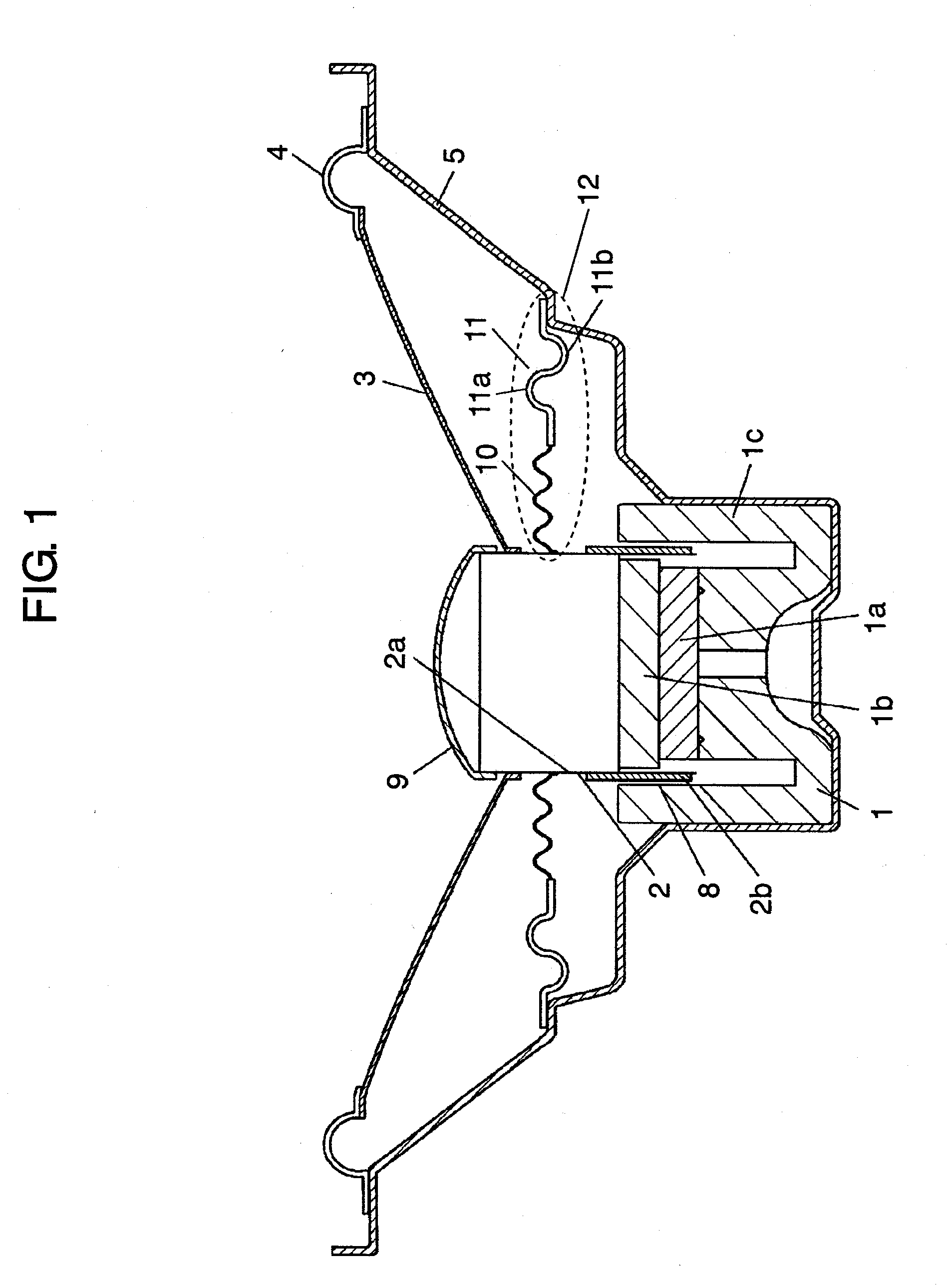
[0049]FIG. 3 shows a sectional view of a speaker in accordance with the second embodiment, in which second edge 11c changes its shape from what is shown in FIG. 2 and used in the first embodiment.

[0050]To be more specific, in the first embodiment shown in FIG. 2, first protrusion 11a located on more inner side of the speaker than second one protrudes toward diaphragm 3, and second protrusion 11b located on more outer side of the speaker than the first one protrudes opposite to the first one; however, the directions of the protrusions are not always limited to this instance. The second embodiment shown in FIG. 3 thus protrudes second protrusion 11e located on more outer side of the speaker than the first one towar...


PUM


Abstract

A speaker having smaller distortion and driven at higher efficiency is disclosed. The speaker includes a frame, a magnetic circuit supported by the frame, a voice coil unit placed movable with respect to magnetic gap provided to the magnetic circuit, a diaphragm of which outer rim is coupled to the frame via a first edge, and of which inner rim is coupled to the voice coil unit, and a damper placed on the magnetic circuit side with respect to the diaphragm, and which damper has an outer rim coupled to the frame and an inner rim coupled to the voice coil unit. The outer rim of the damper is coupled to the frame via a second edge, which includes a first protrusion protruding toward the diaphragm and a second protrusion protruding oppositely to the first protrusion.

Description

TECHNICAL FIELD[0001]The present invention relates to speakersBACKGROUND ART[0002]FIG. 4 shows a partial sectional view of a conventional speaker, which comprises the following elements:[0003]magnetic circuit 1A;[0004]voice coil unit 2A movably placed on magnetic circuit 1A;[0005]diaphragm 3A of which inner rim is coupled to voice coil unit 2A;[0006]edge 4A with which an outer rim of diaphragm 3A is coupled to frame 5A; and[0007]suspension holder 6A and edge 7A with both of which a rear face of diaphragm 3A is coupled to frame 5A.Edge 4A and edge 7A protrude oppositely to each other, so that vertical excursion of diaphragm 3A becomes symmetric with respect to a horizontal axis in FIG. 4, thereby reducing distortion of the speaker.[0008]Such a conventional speaker as discussed above is disclosed in, e.g. Unexamined Japanese Patent Publication No. 2004-7332 referred to as cited reference 1.[0009]The foregoing conventional speaker, however, employs suspension holder 6A which firmly hol...

Claims


Application Information

Patent Timeline
Patent Type & Authority Applications(United States)
IPC IPC(8): H04R11/02
CPCH04R9/043H04R9/02H04R9/04
Inventor FUNAHASHI, OSAMU
Owner PANASONIC CORP
Why Eureka
Try Eureka