Peripherally pivoted oscillating vane machine

a technology of oscillating vane and rotating shaft, which is applied in the direction of machines/engines, oscillating piston pumps, liquid fuel engines, etc., can solve the problems of insufficient high pressure, single oscillating vane at high speed producing excessive vibration, and over-running clutches not providing reliable synchronized motion, etc., to achieve high flow and high pressure, improve efficiency and flexibility, and reduce the effect of over-running clutches

Inactive Publication Date: 2009-03-26
MECHANOLOGY INC
View PDF13 Cites 16 Cited by
  • Summary
  • Abstract
  • Description
  • Claims
  • Application Information

AI Technical Summary

Benefits of technology

[0010]The present invention is directed to a peripherally pivoted oscillating vane machine (OVM) which can be adapted for use either as a compressor or as an expander and which has the potential to produce high flow and high pressures from small and inexpensive packages. More specifically, the presen

Problems solved by technology

This type of seal is, at best, a line contact and is insufficient for high pressures.
As such, the porting arrangement of Mize does not allow the oscillating vanes to provide an efficient inlet process by themselves; therefore, Mize utilizes an integrated centrifugal blower to charge the chambers with fresh air.
This type of arrangement is better suited for higher pressures; however, the actuation of a single oscillating vane at high s

Method used


Image

  • Peripherally pivoted oscillating vane machine
  • Peripherally pivoted oscillating vane machine
  • Peripherally pivoted oscillating vane machine

Examples


Embodiment Construction

[0091]A description of the preferred embodiments of the invention follows.

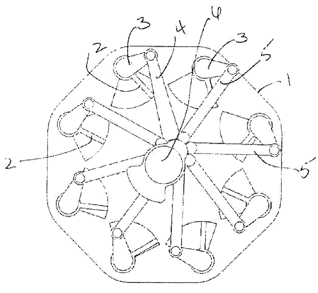
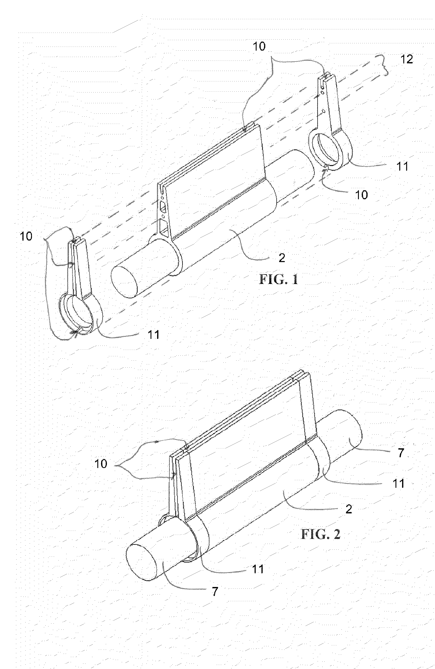
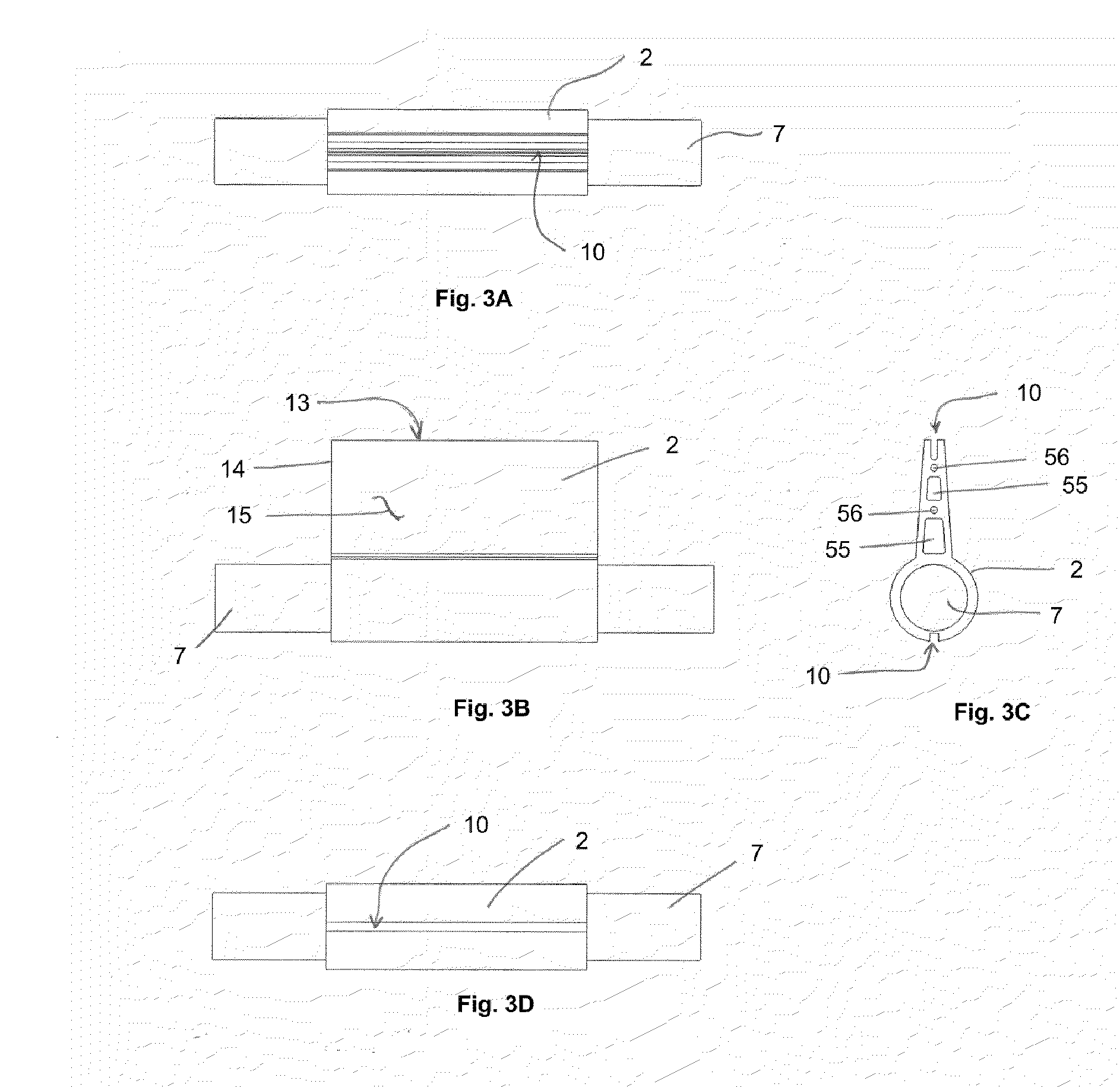
[0092]As has been appreciated in the prior art, and in earlier work performed by Chomyszak, the OVM provides a remarkable ratio of capacity to compress or expand fluid compared to its size and weight. Applicants have discovered that what limits the OVM from achieving its potential is that the loads imparted onto the drive mechanisms which interface with the oscillating vanes 2 can be extremely high.

[0093]For a given power level, there are four ways to improve the drive mechanism such that it is capable of withstanding the power being transmitted through it: 1) use stronger materials, 2) use larger components, 3) reduce the loads or 4) modify component geometry. The work performed thus far in designing, analyzing, building, and testing a working OVM has shown that the loads on the components are created by three sources: friction, inertia and pressure differential.

[0094]The frictional component is relatively sm...


PUM


Abstract

The present invention is directed to a peripherally pivoted oscillating vane machine (OVM). The OVM has been optimized for performance and efficiency. This has been accomplished by reducing loads on the drive mechanism and by employing de-phased motion of the peripherally pivoted vanes in conjunction with improved porting configurations as well as valve actuation and manufacture.

Description

RELATED APPLICATIONS[0001]This application claims the benefit of U.S. provisional application No. 60 / 974,140 filed on Sep. 21, 2007. The contents of the above application is incorporated herein by reference.BACKGROUND OF THE INVENTION[0002]Oscillating vane machines (OVMs) have been described in the art and have the potential to provide high flow rates and pressures but, in order to do so; they require configurations, such as vane actuation and valving, suitable for high speed operation. See U.S. Pat. No. 2,257,884, issued Oct. 7, 1941 to Mize; U.S. Pat. No. 2,393,204, issued Jan. 15, 1946 to Taylor; U.S. Pat. No. 4,099,448, issued Jul. 11, 1978 to Young; U.S. Pat. No. 4,823,743, issued Apr. 25, 1989 to Ansdale; and U.S. Pat. No. 4,080,114, issued Mar. 21, 1978 to Moriarty; the contents of which are incorporated herein by reference in their entirety.[0003]The machine of Mize places a plurality of oscillating vanes in a common main chamber and relies on the ability of the vanes to sea...

Claims


Application Information

Patent Timeline
IPC IPC(8): F01C9/00
CPCF01C21/0836F01C9/002
Inventor CHOMYSZAK, STEPHEN M.MARTIN, JEDDFERENTINOS, JAMES T.MA, HAI-PINGLEON, FRANCISCO
Owner MECHANOLOGY INC
Why Eureka
Try Eureka