Bandaging structure and methodology

a bandaging structure and wound technology, applied in the field of wound bandaging, can solve the problems of insufficient pressure-applying bandage, bandaging condition, and many conventional bandaging approaches that do not achieve ideal pressure-applying conditions in the bandaged wound area

Inactive Publication Date: 2009-03-26
MJD INNOVATIONS
View PDF6 Cites 5 Cited by
  • Summary
  • Abstract
  • Description
  • Claims
  • Application Information

AI Technical Summary

Benefits of technology

[0011]As will be seen, what is contemplated by the present invention are a structure and a methodology involving special, “pliable-application”, dynamic-action wound bandaging. In particular, the bandaging structure and methodology utilize two, cooperative, dynamically behaving mechanisms, that ar...

Problems solved by technology

As those skilled in the medical arts clearly understand, many conventional bandaging approaches do not achieve ideal pressure-applying conditions in a bandaged wound area.
Very specifically, it is common, in many prior art practices, that a pressure-applying bandage will not properly, and most desirably, in a most appropriate, pressure-applying manner, actually topographically follow the underlying contours of the anatomy in a wound area.
This kind of situation frequently produces, as one unfortunate result, a bandaging condition which ends up applying unacceptably high levels of pressure to certain w...

Method used


Image

  • Bandaging structure and methodology
  • Bandaging structure and methodology
  • Bandaging structure and methodology

Examples


Embodiment Construction

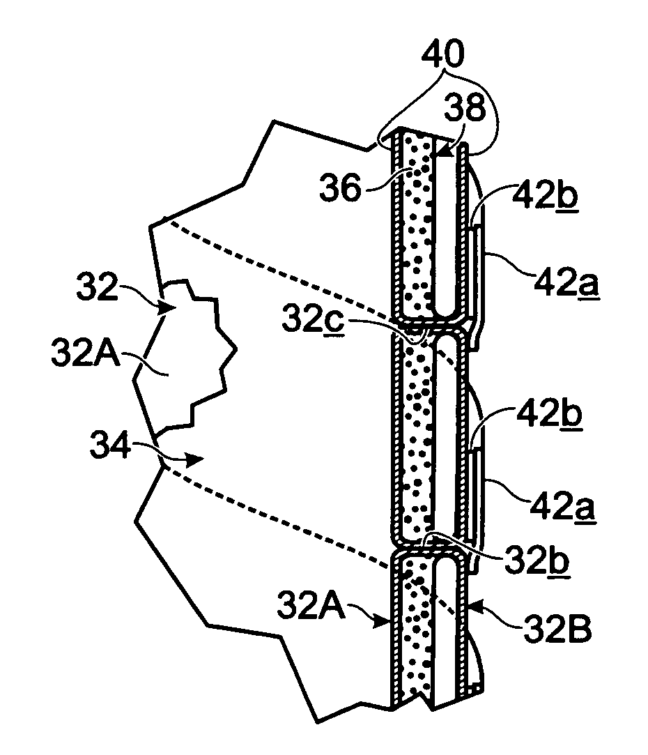
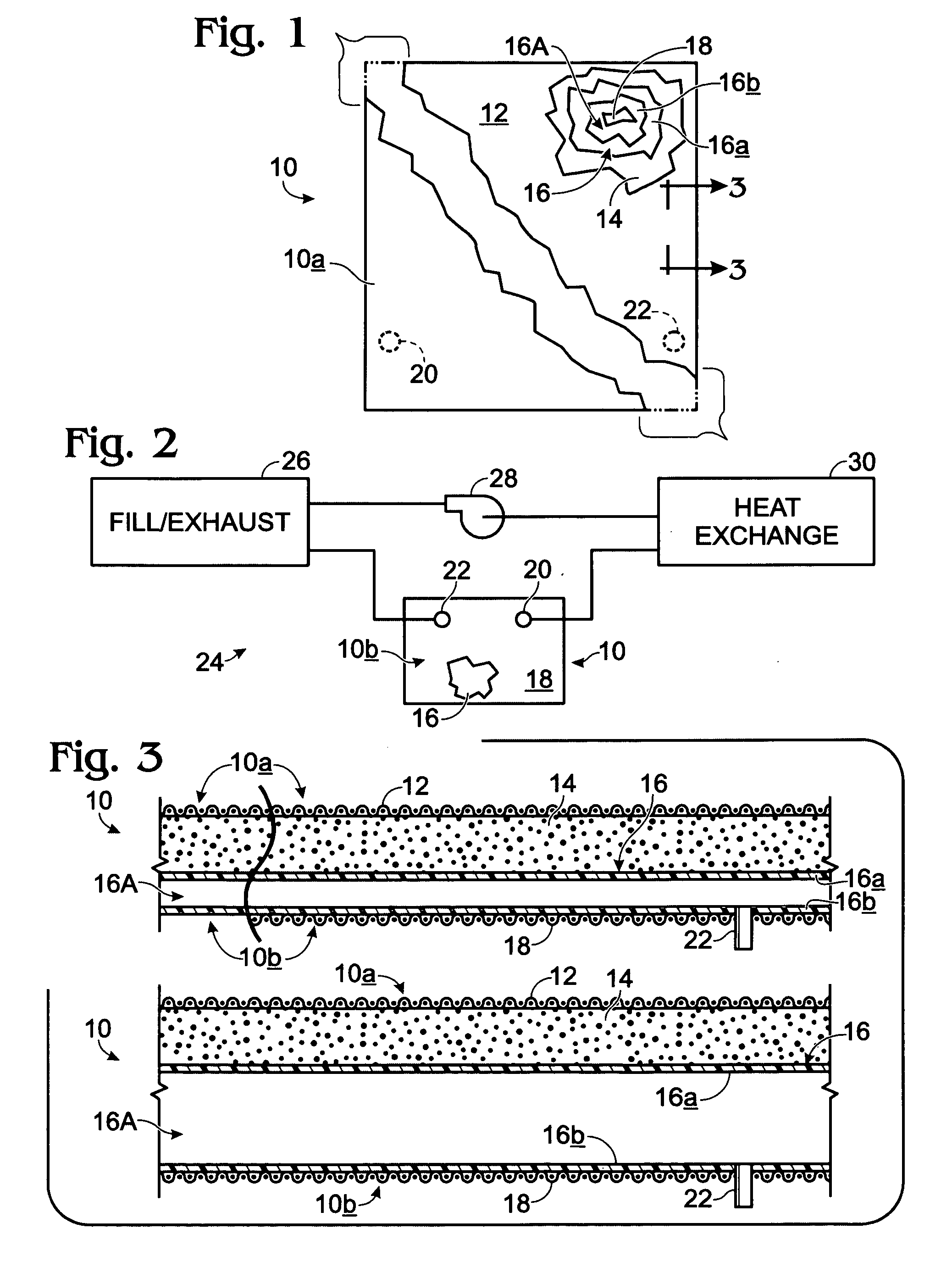
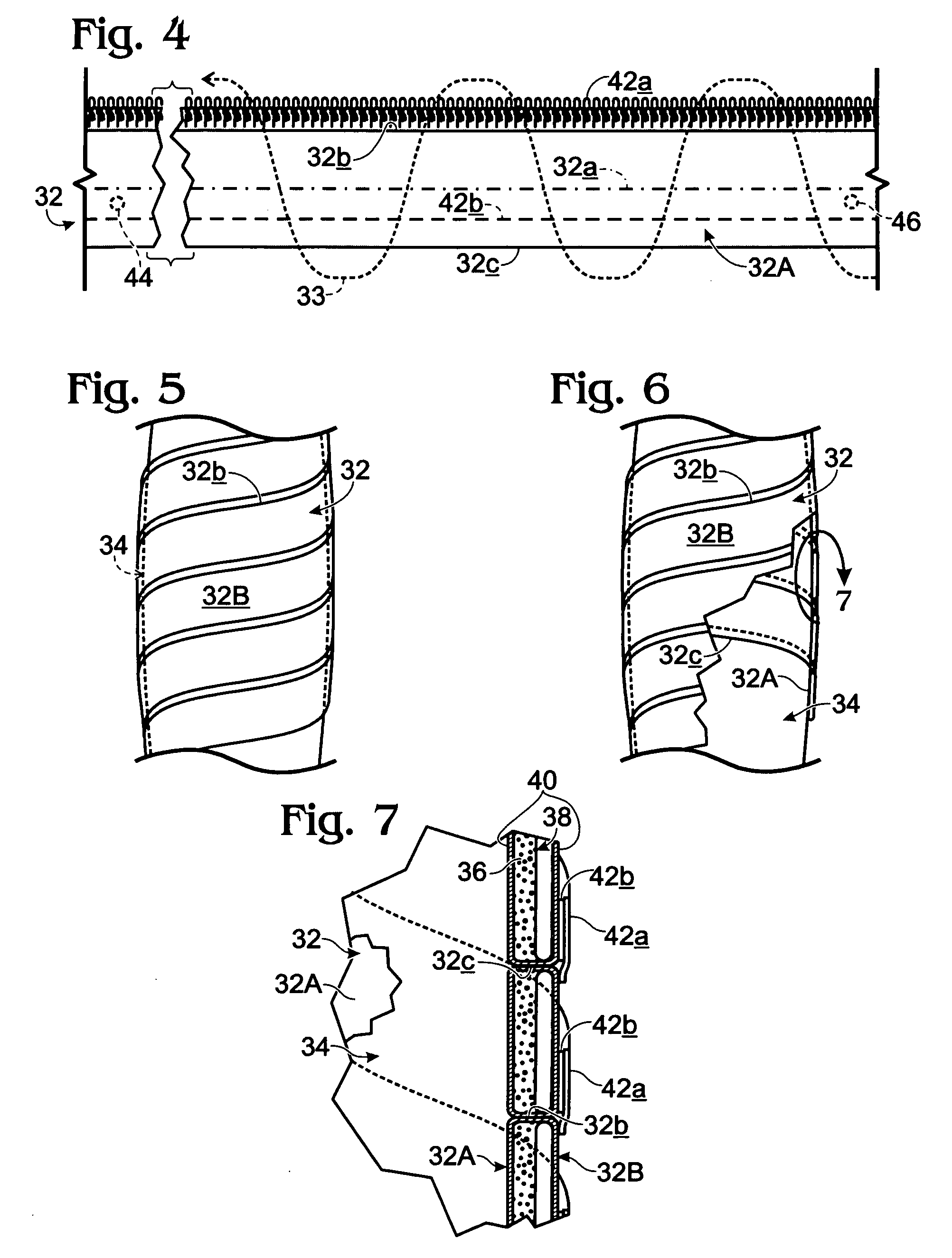
[0022]Turning now to the drawings, and referring first of all to FIGS. 1-3, inclusive, indicated generally at 10 is a preferred and best-mode patch-form modification, or embodiment, of a dynamic-action, pliable, anatomically conformable (in a pressure and temperature sense), layered wound-bandaging structure constructed in accordance with the present invention. Structure 10 includes what is referred to herein as an anatomy side 10a and a non-anatomy side 10b. When bandaging structure 10 is in place in relation to a wound area, it substantially completely covers that area, as determined, of course, by one having chosen an appropriate bandaging-structure size—entirely a matter of choice under the control of the user—with anatomy side 10a disposed, effectively, directly adjacent and against the wound area, and non-anatomy side 10b facing outwardly away from that area.

[0023]As was mentioned above herein with respect to the descriptions of the several drawings, in FIG. 3, the upper and l...


PUM


Abstract

A dynamic-action, pliable, anatomically conformable bandaging structure for application to an anatomical wound including a pliable, low-rebound, viscoelastic, acceleration-rate-sensitive cushioning expanse which is placeable confrontingly adjacent such a wound, and operatively associated and structurally united with that cushioning expanse, adjustable, pressure-fluid-inflatable structure. An associated methodology features the steps of (a) applying over a wound area a first, dynamic-action bandaging structure in the form of the mentioned cushioning material, (b) by such applying, furnishing dynamic, low-rebound, viscoelastic, acceleration-rate-sensitive pressure-applying behavior, and (c) utilizing the mentioned pressure-fluid-inflatable structure, applying, through the cushioning material, collaborative, dynamic, controlled, contained pressure-fluid action.

Description

CROSS REFERENCES TO RELATED CASES[0001]This application claims priority to currently copending U.S. Provisional Patent Application Ser. No. 61 / 003,969, filed Nov. 21, 2007, for Bandaging Structure and Methodology, and is a Continuation-In-Part of currently copending U.S. Regular patent application Ser. No. 11 / 983,259, filed Nov. 7, 2007, for Bandaging Structure and Methodology which claims priority to U.S. Provisional Patent Application Ser. No. 60 / 859,770, for Bandaging Structure and Methodology, filed Nov. 16, 2006, which second-mentioned provisional application describes improvements and variations to the subject matter disclosed, illustrated and claimed in U.S. Pat. No. 6,812,375 B2, granted Nov. 2, 2004, for Pressure-Evenizing Low-rebound Wound Dressing. The disclosure contents of the two mentioned provisional patent applications, of the mentioned regular patent application, and of the mentioned patent, are hereby incorporated herein by reference.BACKGROUND AND SUMMARY OF THE I...

Claims


Application Information

Patent Timeline
IPC IPC(8): A61F13/00
CPCA61F13/00021A61F13/0273A61F2013/00544A61F2013/0028A61F2013/00119
Inventor PAASCHE, GERHARD
Owner MJD INNOVATIONS
Why Eureka
Try Eureka