
Braided vascular devices having no end clamps

Inactive Publication Date: 2009-03-26
ST JUDE MEDICAL CARDILOGY DIV INC
View PDF51 Cites 241 Cited by
  • Summary
  • Abstract
  • Description
  • Claims
  • Application Information

AI Technical Summary

Benefits of technology

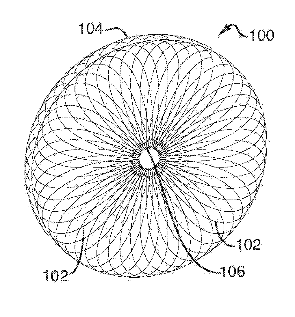
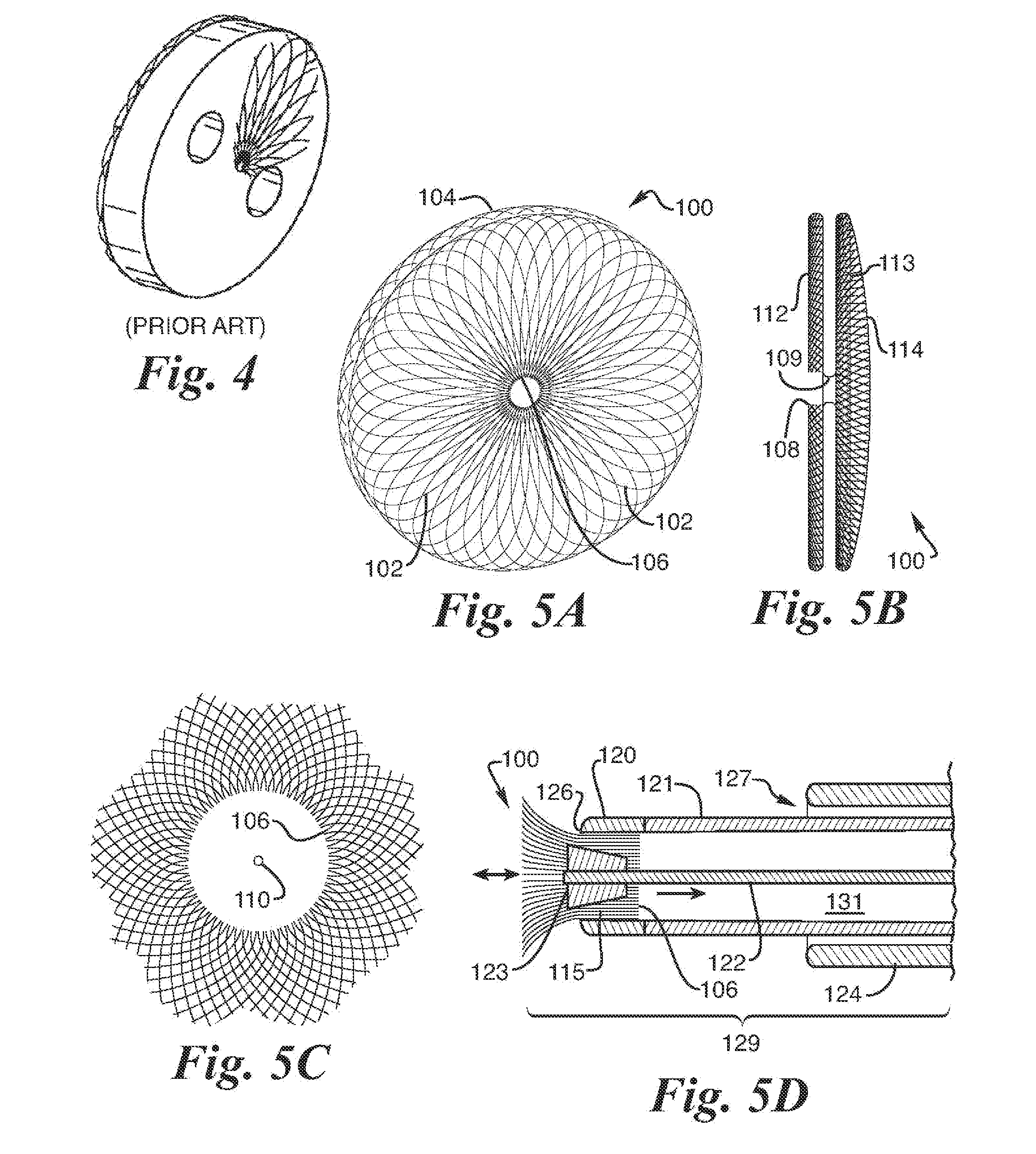
[0021]In some embodiments, a collapsible medical device may include one or more of the following features: (a) at least one layer of a plurality of metal strands woven into a tubular braided metal fabric having a proximal end, a distal end, and a segment there between, (b) the tubular woven metal fabric having an expanded preset configuration shaped for treatment of an opening in a body organ, (c) the expanded preset configuration being deformable to a lesser cross-sectional dimension for del

Problems solved by technology

Over time, this causes a thickening of the pulmonary arteries and ultimately leads to closure of smaller lung arteries and further complications if left untreated.
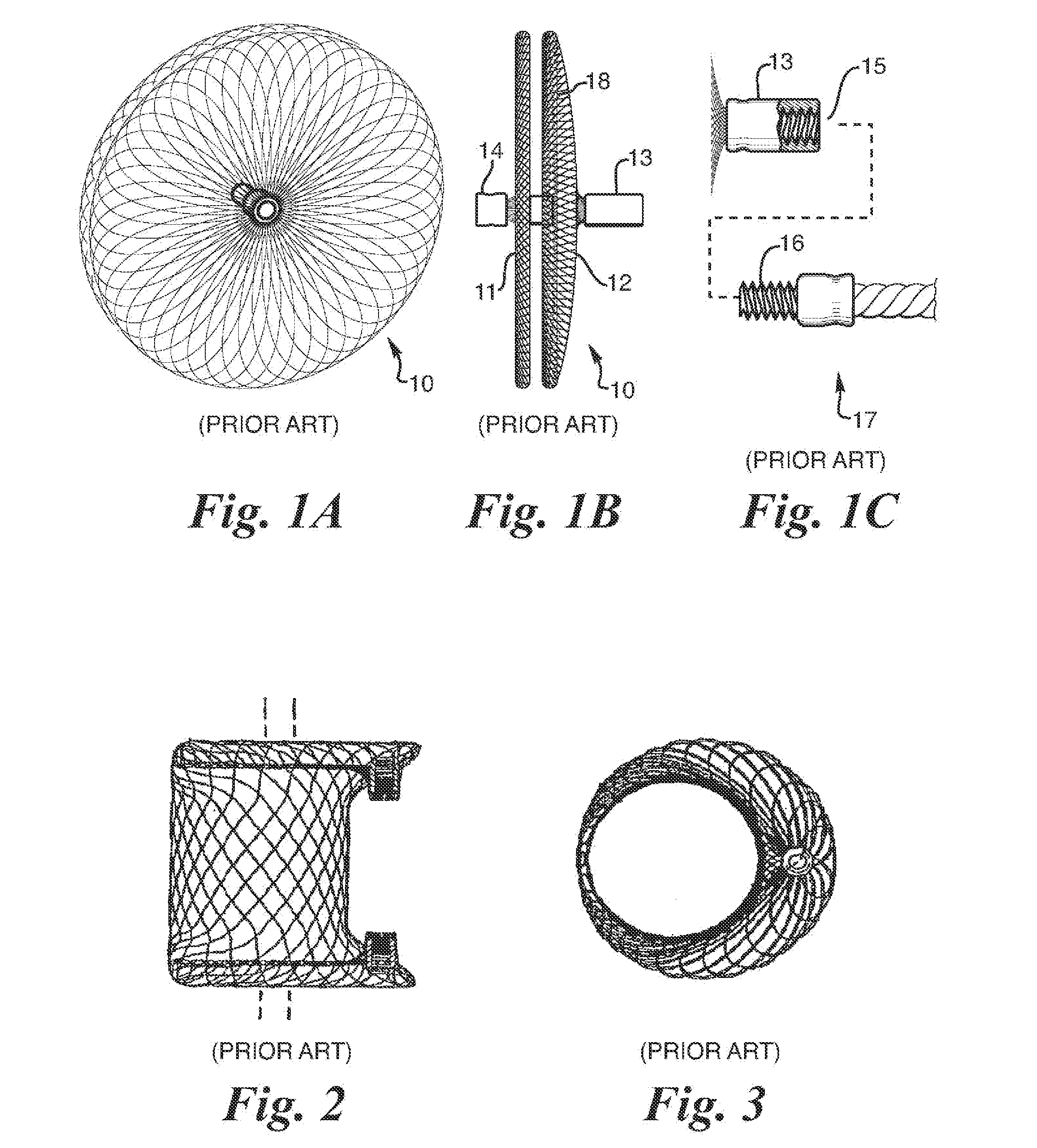
One limitation of these devices is the need to clamp the ends of the wire strands at each end of the device to prevent unraveling.
Although soldering and brazing of NiTi alloys have proven to be fairly difficult, the ends can be welded together, such as by spot welding with a laser welder.
These outward projections are often in the blood flow path and could be a source of clot formation or result in flow disruption.
However, the recessed clamps cause the fabric to reverse direction in the heat-set state.
In the compressed state, the wires are higher stressed and exert an increased outward drag against the wall of the delivery catheter making it more difficult to push the device through the catheter.
In the case of a flow restrictor or shunt device, the braided wire end clamps make the device configuration bulky and un-necessarily complex, since the natural placement of the clamps is in a co-axial position to the braided tube, which ideally, is where the flow path should be.
In addition the manufacturing cost of the device is higher than need be if the clamps were not used.

Method used


Image

  • Braided vascular devices having no end clamps
  • Braided vascular devices having no end clamps
  • Braided vascular devices having no end clamps

Examples


Embodiment Construction

[0045]The following discussion is presented to enable a person skilled in the art to make and use the present teachings. Various modifications to the illustrated embodiments will be readily apparent to those skilled in the art, and the generic principles herein may be applied to other embodiments and applications without departing from the present teachings. Thus, the present teachings are not intended to be limited to embodiments shown, but are to be accorded the widest scope consistent with the principles and features disclosed herein. The following detailed description is to be read with reference to the figures, in which like elements in different figures have like reference numerals. The figures, which are not necessarily to scale, depict selected embodiments and are not intended to limit the scope of the present teachings. Skilled artisans will recognize the examples provided herein have many useful alternatives and fall within the scope of the present teachings. It's understo...


PUM


Abstract

In some embodiments, a medical device may include one or more of the following features: (a) a metal fabric formed of braided metal strands, (b) the medical device having a collapsed configuration for delivery through a channel in a patient's body and having a generally dumbbell-shaped expanded configuration with two expanded diameter portions separated by a reduced diameter portion formed between opposed ends of the device and unsecured metal strand ends at the opposed ends, and (d) a thrombogenic agent located on the metal fabric.

Description

FIELD OF THE INVENTION [0001]Embodiments of the present invention generally relate to intravascular devices for treating medical conditions. Particularly, embodiments of the present invention relate to intravascular devices for treating vascular conditions. More particularly, embodiments of the present invention relate to intravascular devices for selective occlusion of a vessel and / or shunting or restricting flow in a vessel or organ within the body's circulatory system.BACKGROUND [0002]A wide variety of intravascular devices are used in various medical procedures. Certain intravascular devices, such as balloon catheters, diagnostic catheters, stent delivery catheters, and guidewires are generally used simply to deliver fluids or other medical devices to specific locations within a patient's body, such as a selective site within the vascular system. Other frequently more complex, devices are used in treating specific conditions, such as devices used in removing vascular occlusions ...

Claims


Application Information

Patent Timeline
IPC IPC(8): A61B17/03
CPCA61B17/0057A61B17/12022A61B17/12036A61B17/12109A61B17/12113A61B2017/12095A61B2017/00575A61B2017/00623A61B2017/00867A61B2017/12054A61B17/12172A61B17/12177A61B2017/00615
Inventor ADAMS, DANIEL O.PIGNATO, PAUL
Owner ST JUDE MEDICAL CARDILOGY DIV INC
Learn More