Method and system for efficient data collection and storage

a data collection and data technology, applied in the direction of electrical control, instruments, code conversion, etc., can solve the problems of large data volume, large data collection rate, and insufficient on-board storage of new aircraft,

Active Publication Date: 2009-03-26
GENERAL ELECTRIC CO
View PDF30 Cites 46 Cited by
  • Summary
  • Abstract
  • Description
  • Claims
  • Application Information

AI Technical Summary

Benefits of technology

[0006]Embodiments of the present invention address this and other needs. In one embodiment, a system for collecting and storing performance data for an engine is provided. The system includes one or more sensors configured to generate a plurality of sensor data signals representative of one or more engine data performance parameters. The system further includes a data sampling component, a data quantizing component, a data storage sampling rate component, a data encoding component and a data storage component. The data sampling component is configured to sample the sensor data signals at a data sampling rate. The data quantizing component is configured to generate a plurality of quantized data samples corresponding to the sampled sensor data signals. The data storage sampling rate component is configured to determine a data storage sampling rate for the quantized data samples, based on an analysis of at least a subset of the quantized data samples. The data encoding component is configured to encode the quantized data samples according to the data storage sampling rate and the data storage component is configured to store the encoded data samples from the encoding component.

Problems solved by technology

Furthermore, some new aircraft will simply not have enough on-board storage to retain the vast amount of data that is produced at a high rate of sampling.
To add to this, the sampling rate of the data that can be collected is typically limited by the capacity of the recorder's storage medium, the physical constraints of the recorder's storage capacity and the expected duration of the flight.

Method used


Image

  • Method and system for efficient data collection and storage
  • Method and system for efficient data collection and storage
  • Method and system for efficient data collection and storage

Examples


Embodiment Construction

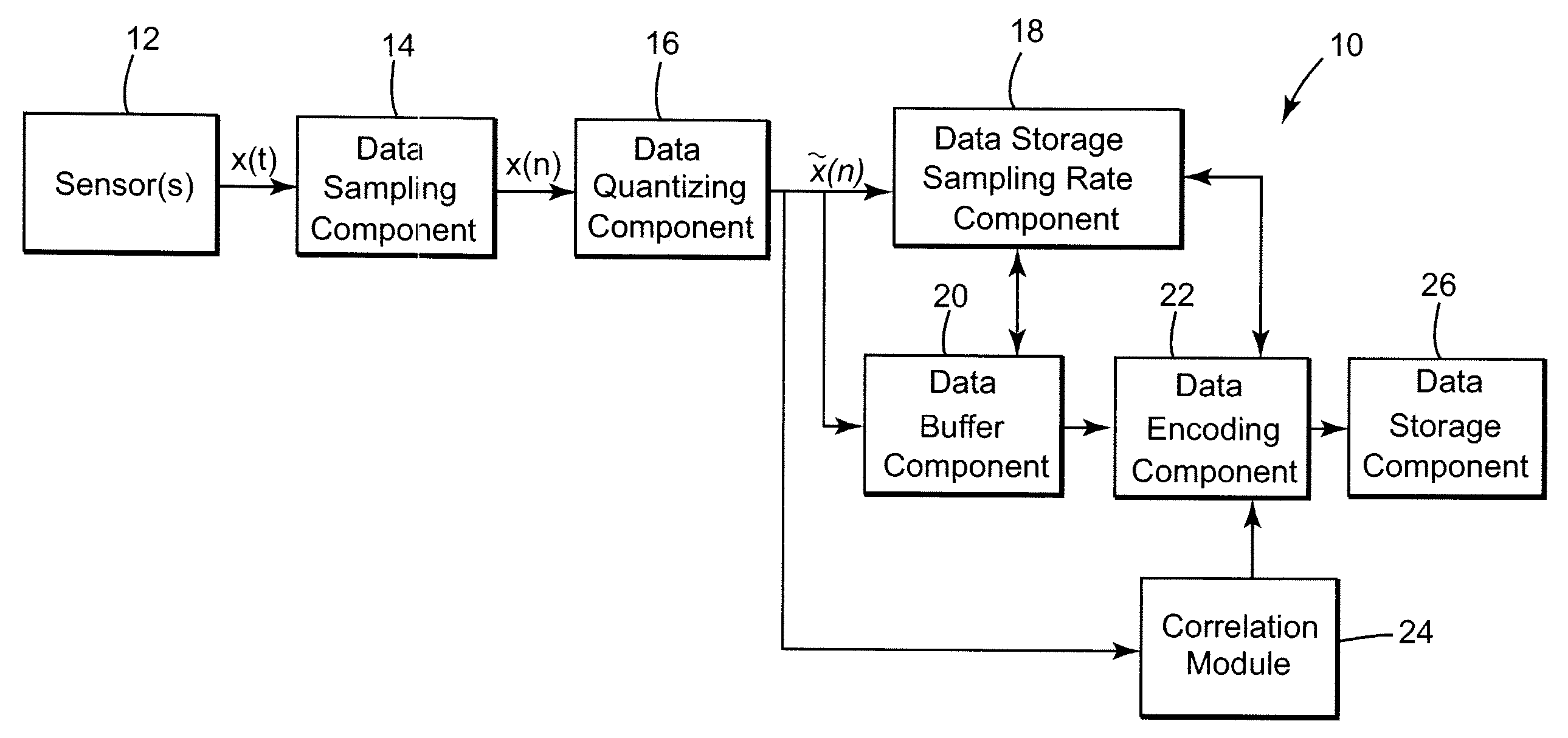
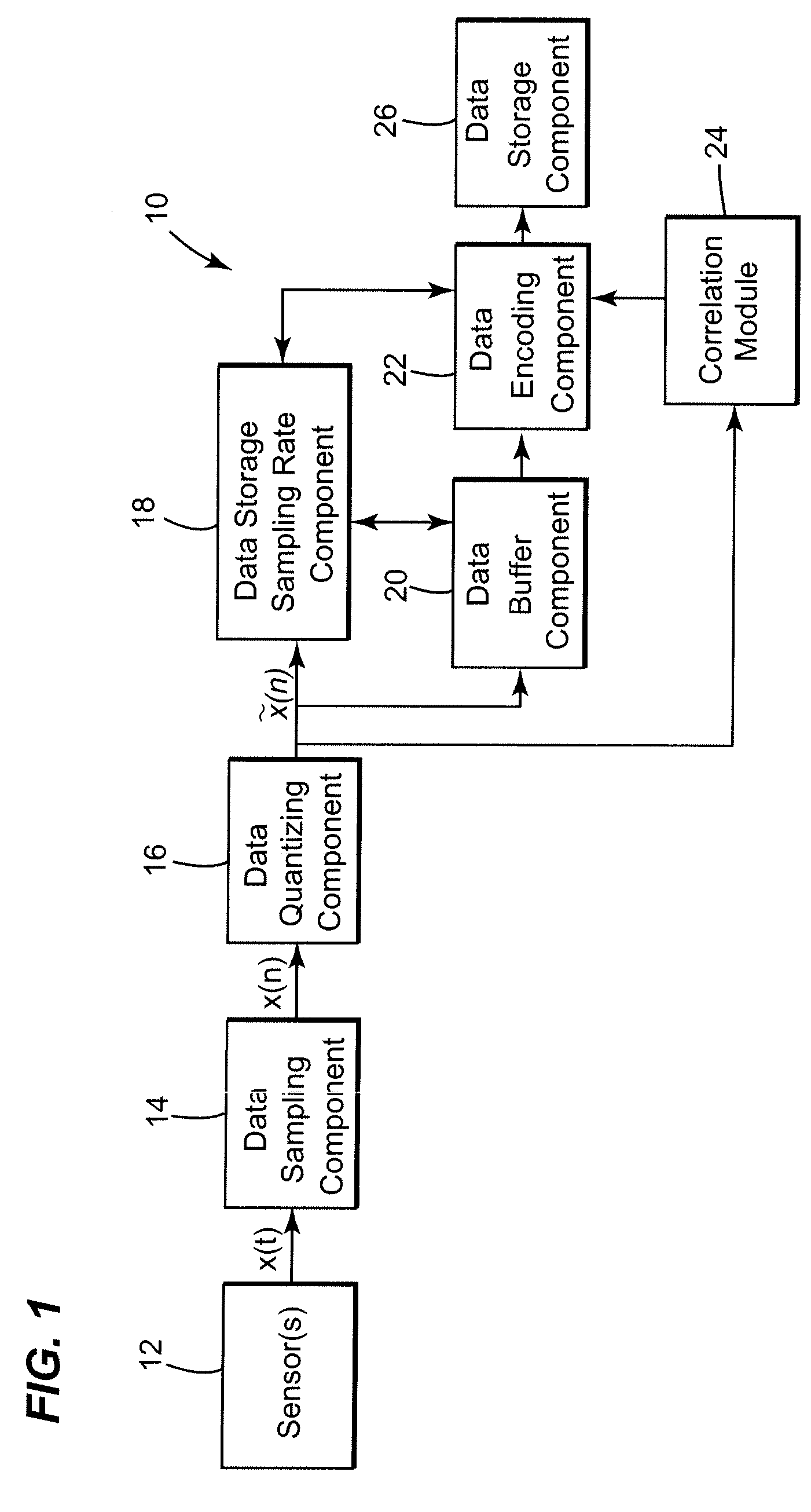
[0016]FIG. 1 is an exemplary illustration of a system for collecting and storing performance data for an engine, in accordance with one embodiment of the present invention. In one embodiment, the system 10 is configured to collect and store data from an aircraft having at least one engine. It may be noted, however, that the data collection and storage for additional engines may be accomplished by the system 10 in a manner identical to that for a single engine. Further, the disclosed system may also be configured to collect and store data for other types of engines, such as, for example, land based power generation engines, marine transportation engines and machine tools, as well as other types of mechanical systems.

[0017]Referring to FIG. 1, the system 10 generally includes one or more sensors 12, a data sampling component 14, a data quantizing component 16, a data storage sampling rate component 18 and a data encoding component 22. In one embodiment, the sensors 12 are configured t...


PUM


Abstract

A system for collecting and storing performance data for an engine is provided. The system includes one or more sensors configured to generate sensor data signals representative of one or more engine data performance parameters. The system further includes a data sampling component, a data quantizing component, a data storage sampling rate component, a data encoding component and a data storage component. The data sampling component is configured to sample the sensor data signals at a data sampling rate. The data quantizing component is configured to generate quantized data samples corresponding to the sampled sensor data signals. The data storage sampling rate component is configured to determine a data storage sampling rate for the quantized data samples, based on an analysis of at least a subset of the quantized data samples. The data encoding component is configured to encode the quantized data samples according to the data storage sampling rate, and the data storage component is configured to store the encoded data samples from the encoding component.

Description

BACKGROUND[0001]The invention relates generally to monitoring the health of an engine and more particularly to a system and method for collecting and storing monitored engine data indicative of the health of an engine.[0002]An engine is typically monitored to assess the performance of the engine in its healthy operative state so that the engine may be controlled in a near optimal manner. An engine is also monitored to detect anomalous conditions indicative of degrading engine health so that malfunctions or faults in the engine may be diagnosed in a timely manner. In general, it is desirable that sufficient data from a monitoring suite of sensors is collected and stored, so that technical personnel can be provided with an insight into the fault or failure and be able to diagnose, post incident, the conditions leading to the particular fault or failure. Beyond the need to have a suite of sensors to monitor the requisite engine parameters at an appropriate rate and be able to adequatel...

Claims


Application Information

Patent Timeline
Patent Type & Authority Applications(United States)
IPC IPC(8): F02D45/00
CPCF02D41/249F02D2041/288F02D2041/285F02D41/28
Inventor HERSHEY, JOHN ERIKBRUNO, JEANETTE MARIEOSBORN, BROCK ESTELIYER, NARESH SUNDARAMABERNATHY, CHARLES LARRYFULLINGTON, MICHAEL DEAN
Owner GENERAL ELECTRIC CO
Why Eureka
Try Eureka