Supercharge Your Innovation With Domain-Expert AI Agents!

Soap dispensing apparatus for counter-mounted automatic soap dispensor

a dispenser and automatic technology, applied in the direction of liquid transfer devices, instruments, volume meters, etc., can solve the problems of soap dispensers with a wholly too complex mechanism to make maintenance convenient, and malfunctions may occur, so as to reduce the chances of malfunction, simplify the whole mechanism, and avoid malfunctions.

Inactive Publication Date: 2009-04-02
CHEN JAN SUN
View PDF42 Cites 12 Cited by
  • Summary
  • Abstract
  • Description
  • Claims
  • Application Information

AI Technical Summary

Benefits of technology

[0005]In view of the foregoing disadvantages of the prior art, the present invention has an object to provide an automatic countertop soap dispensing apparatus that has a simple structure, particularly a soap dispensing apparatus that has stable operational function, in hope that an automatic soap dispenser applying this invention can reduce possibilities of servicing and cost.
[0007]As the above soap dispensing apparatus uses the driving force provided by the meshing of the soap displacing gears, it requires no further pump mechanisms; consequently, the whole mechanism can be simplified, and opportunities of malfunction avoided. Moreover, the delivery tubes of the soap dispensing apparatus according to the present invention are always in a fixed state of connection whether during dispensing operation or not, opportunities of malfunction therein can thus be minimized. Therefore, a simple yet reliable soap dispensing apparatus, which when embodied in an automatic countertop soap dispenser will bring such dispenser the benefits of being easy to maintain and unlikely to malfunction, is provided in the present invention.

Problems solved by technology

But, as the dispensing tube is adapted to move in the dispensing spout when the pump mechanism is actuated, malfunction may occur.
In addition, such automatic soap dispenser has a mechanism that is wholly too complex to make maintenance convenient.

Method used


Image

  • Soap dispensing apparatus for counter-mounted automatic soap dispensor
  • Soap dispensing apparatus for counter-mounted automatic soap dispensor
  • Soap dispensing apparatus for counter-mounted automatic soap dispensor

Examples


Embodiment Construction

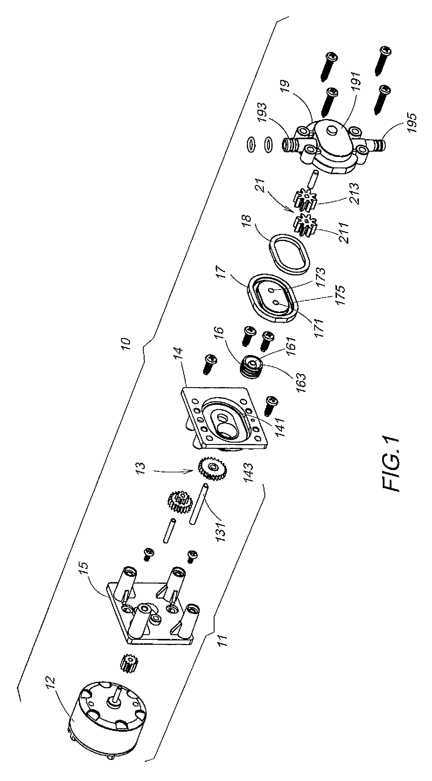
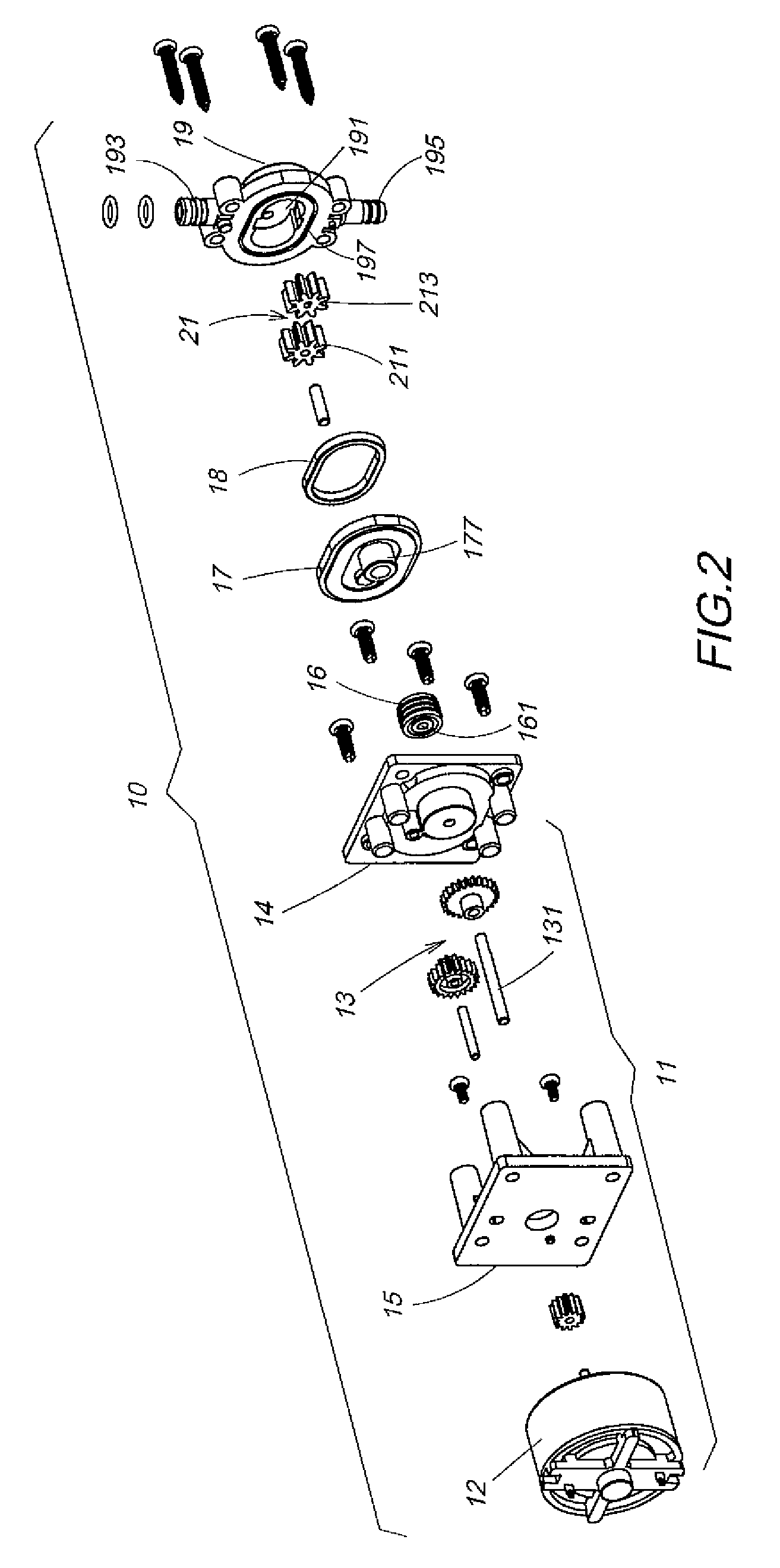
[0013]Reference will be made to the drawings and the presently preferred embodiment to describe in detail the structural characteristics and the effects of the present invention. For a preferred embodiment of the soap dispensing apparatus of the present invention for an automatic countertop soap dispenser, please refer to FIG. 1 and FIG. 2, which show the same elements of such soap dispensing apparatus in two exploded perspective views seen from opposite directions. Such soap dispensing apparatus 10 comprises: a drive device 11, which includes a motor 12 and a reduction gear set 13 driven thereby; a rear board 14 having a recessed trough 141, on which bottom a main axial groove 143 is provided; a first packer 16, which has the same profile as that of said main axial groove 143 of said rear board 14, with an axial bore 161 tightly embracing the output shaft 131 of the gear set 13 yet allowing the shaft to spin freely, said axial bore 161 having a recessed area around it to form an an...


PUM


Abstract

A soap dispensing apparatus for an automatic countertop soap dispenser, comprising a motor and a reduction gear set driven thereby, said reduction gear set with an output shaft coupled to the drive gear of a pair of soap displacing gears in mesh side by side, said soap displacing gears disposed, by precision fit, in a chamber that extends upward and downward to form an outlet passage and an inlet passage, wherein the outlet passage is connected to a countertop soap dispensing spout, and the inlet passage to a soap containing reservoir. Whereby an upward suction force induced by the rotation in mesh of the drive gear and the idler gear of said soap displacing gears is used to suck the liquid soap through the inlet passage and out of the outlet passage, thus to lift the liquid soap above countertop to achieve soap dispensing.

Description

BACKGROUND OF THE INVENTION[0001]1. Field of the Invention[0002]The present invention relates to a soap dispensing apparatus, in particular, to a soap dispensing apparatus for counter-mounted automatic soap dispensers that uses the upward suction induced by the rotation of a pair of gears in mesh to move liquid soap from a lower position to a relatively higher counter for dispensing.[0003]2. Description of the Prior Art[0004]Automatic soap dispensers are widely used in household or public places to offer hygienic use by means of outputting liquid soap through sensing and doing without touching the soap dispensing apparatus. Automatic soap dispensers are divided in wall-mounted ones and counter-mounted ones, depending on their installed location. Among them is an automatic soap dispenser used on top of counter provided in the U.S. Pat. No. 6,467,651. It has a structure comprising a dispensing spout and a drive box, which is operatively connected to said dispensing spout, wherein the ...

Claims


Application Information

Patent Timeline
IPC IPC(8): B67D5/08B65D88/54B67D7/08
CPCA47K2005/1218A47K5/1217
Inventor CHEN, JAN SUN
Owner CHEN JAN SUN
Features
  • R&D
  • Intellectual Property
  • Life Sciences
  • Materials
  • Tech Scout
  • Unparalleled Data Quality
  • Higher Quality Content
  • 60% Fewer Hallucinations
Learn More