

Wind turbine blade molds
a technology of wind turbine blades and molds, which is applied in the field of molds, can solve the problems of large and complex molds that can be difficult and costly to fabricate, and the cost of preparing molds is a significant percentage of the overall cost of manufacturing blades
- Summary
- Abstract
- Description
- Claims
- Application Information
AI Technical Summary
Problems solved by technology
Method used
Image

Examples
Embodiment Construction
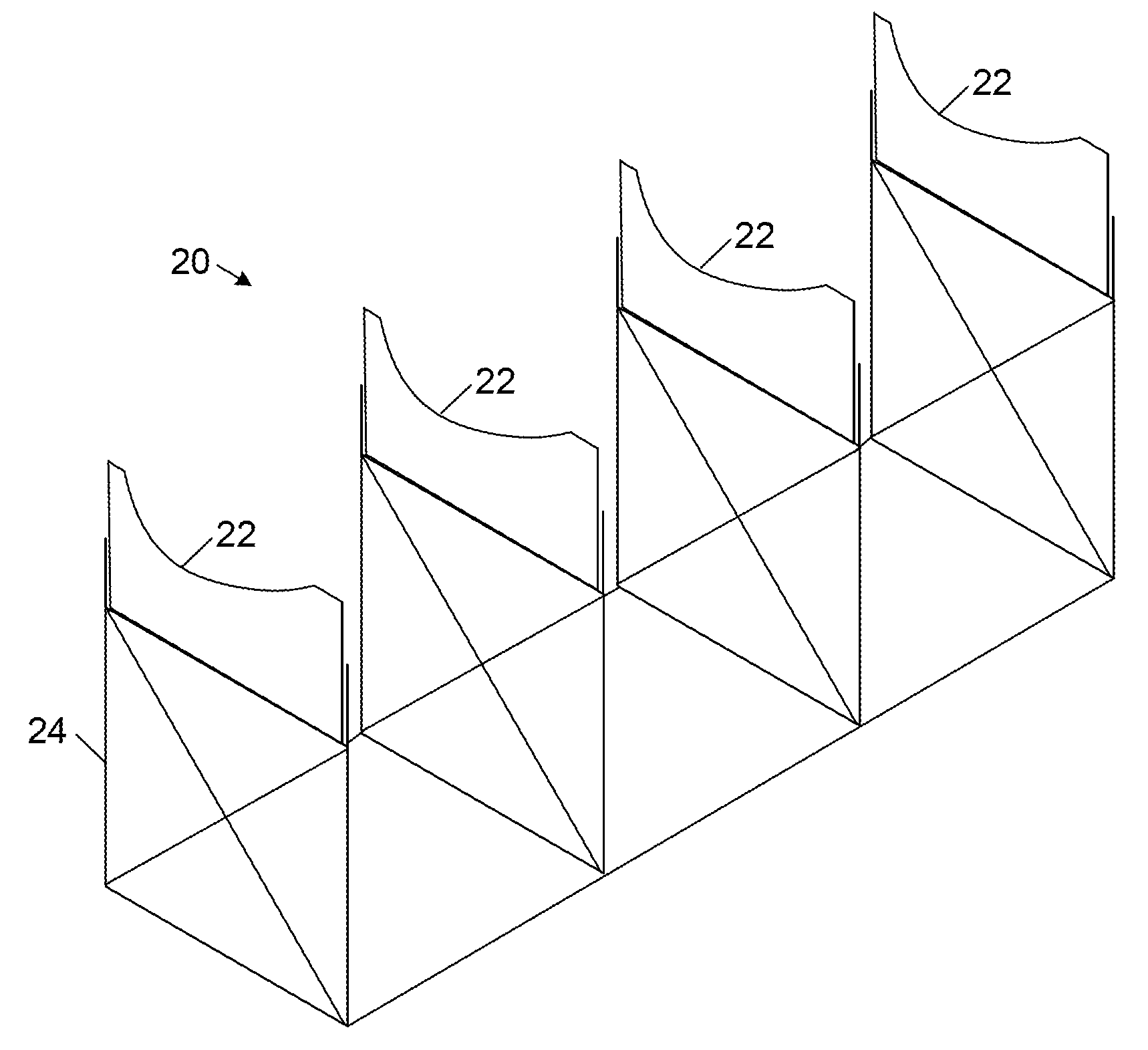
[0014]FIG. 2 schematically illustrates part of a mold for making, all or a portion of, a wind turbine blade 10. Some or all of the blade 10 may also be formed using various techniques, such as those described in co-pending, commonly-owned U.S. patent application Ser. Nos. 11 / 627,490 filed on Jan. 26, 2007 as “Preform Spar Cap for a Wind Turbine Rotor Blade,” and Ser. No. 11 / 311,053 filed on Dec. 19, 2005 as “A Modularly Constructed Rotorblade And Method For Construction.”
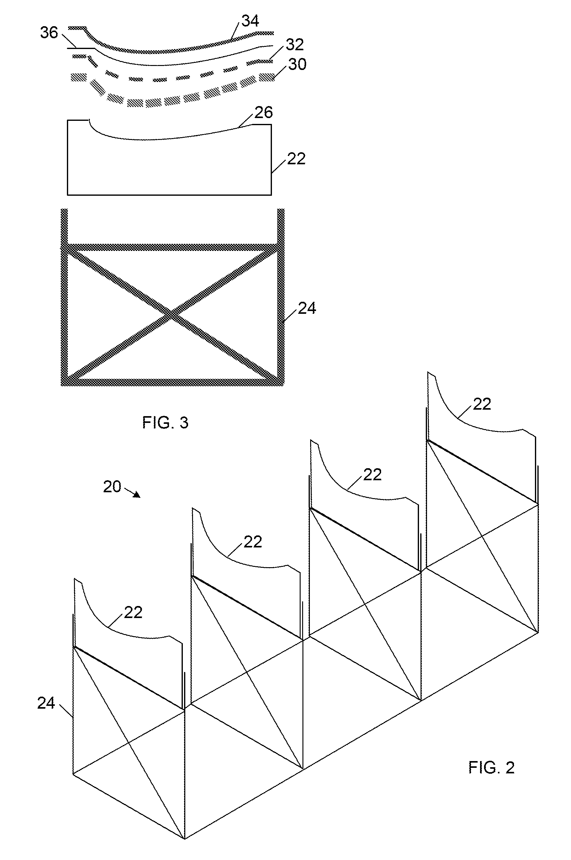
[0015]The mold 20 includes a plurality of joists 22 arranged on a support structure 24. The support structure 24 helps maintain the joists 22 with the appropriate spacing and height relative to each other. For example, the joists 22 may be 0.1 inch thick metal and / or composite plates that are spaced apart approximately twenty to thirty inches. However, a wide variety of other materials and / or dimensions may also be used, including plywood and / or glass reinforced plastic. For example, the joists 22 may be substantial...
PUM
| Property | Measurement | Unit |
|---|---|---|
| Density | aaaaa | aaaaa |
| Flexibility | aaaaa | aaaaa |
| Shape | aaaaa | aaaaa |
Abstract
Description
Claims
Application Information