Rotating wheel mechanism of construction machine and drive wheel mechanism of construction machine

a technology of rotating wheel and construction machine, which is applied in the direction of mechanical equipment, machines/engines, transportation and packaging, etc., can solve the problems of further shortening countermeasures taken against dirt accumulated on the outer circumference, and reducing the service life of floating seals, so as to effectively prevent dirt from entering the portion of floating seals, the effect of preventing further dirt from being accumulated and smooth discharg

Active Publication Date: 2009-04-02
KOMATSU LTD
View PDF28 Cites 19 Cited by
  • Summary
  • Abstract
  • Description
  • Claims
  • Application Information

AI Technical Summary

Benefits of technology

[0016]In accordance with a fourth aspect, an annular space opened downward at the lower part of the circumferential area about the center of rotation of the rotating wheel is formed between the outer circumferential seal and the inner circumferential seal. With such a construction, dirt is prevented from entering the outside seal by the annular space, and the dirt that has entered the annular space is discharged outside through the lower part of the annular space. Therefore, the effect of preventing dirt from entering the portion of the floating seal is further improved.
[0017]In accordance with a fifth aspect, the blades are provided with a first blade protruding toward the outer circumference of the rotating wheel and a second blade protruding toward the center of rotation of the rotating wheel on the inner circumference of the first blade. Therefore, since the blades are rotated in two annular areas, it is possible to effectively prevent dirt from being accumulated.
[0018]In accordance with a sixth aspect, the blades have an inclination by which dirt are discharged from the center of rotation of the rotating wheel to the outside as the rotating wheel rotates. With such a construction, dirt is effectively prevented from entering the portion of the floating seal, and the dirt is smoothly discharged.
[0019]In accordance with a seventh aspect, an inclination of the blade is provided at the leading side of the rotating wheel in the rotation direction and at the trailing side thereof. With such a construction, even if the rotating wheel rotates forward or in reverse, dirt is effectively prevented from entering, and is effectively discharged.
[0020]In accordance with an eighth aspect, the invention is embodied in a drive wheel mechanism of construction machines. Since it is possible to effectively prevent dirt from entering the drive wheel mechanism, the drive wheel is satisfactorily rotated for a prolonged period of time, wherein service life and maintenance cycle thereof can be extended.

Problems solved by technology

For this reason, there is a problem that the sealing property of the floating seal 101 is lost at an early stage, and the service life of the seal is reduced.
This can become a cause for further shortening of the service life of the floating seal 101.
However, in the prior art constructions according to Patent Documents 1 and 2, no countermeasures are taken against dirt accumulated on the outer circumference of the outside seal.
Therefore, it is difficult to remove adverse influences against the floating seal due to the accumulated dirt described above.

Method used


Image

  • Rotating wheel mechanism of construction machine and drive wheel mechanism of construction machine
  • Rotating wheel mechanism of construction machine and drive wheel mechanism of construction machine
  • Rotating wheel mechanism of construction machine and drive wheel mechanism of construction machine

Examples


first embodiment

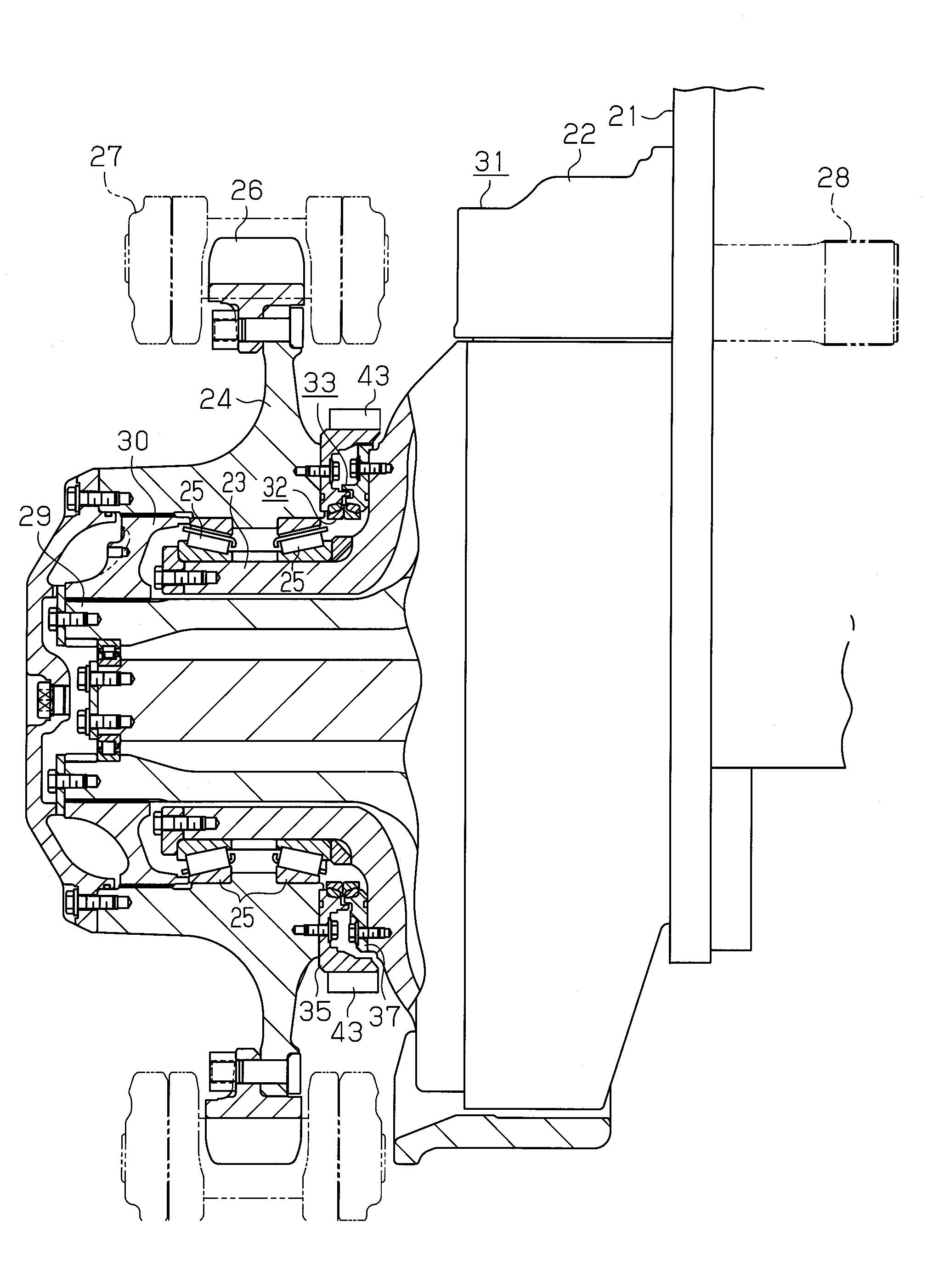
[0047]A crawler track drive wheel mechanism according to a first embodiment of the present invention will now be described with reference to FIGS. 1 to 6. The crawler track is used in a construction machine such as a bulldozer.

[0048]As shown in FIG. 1, in the construction machine, a fixed housing 22 serving as a vehicle body is attached to and fixed at the lower frame 21 of the vehicle body. A drive shaft 28 is rotatably supported on the fixed housing 22, and the drive shaft 28 is rotated forward or in reverse by a hydraulic motor (not illustrated). A cylindrical rotary shaft 29 is rotatably supported in the fixed housing 22, and a drive wheel 24 is rotatably supported with a bearing 25 at a distal end of the fixed housing 22. The drive wheel 24 is coupled to an end of the rotary shaft 29 with a bracket 30.

[0049]The rotary shaft 29 is rotated forward or in reverse with its speed reduced through a reduction gear mechanism (not illustrated) in the fixed housing 22 as the drive shaft 2...

second embodiment

[0061]Next, a description is given of a second embodiment, about the points differing from the first embodiment described above. Also, in respective embodiments coming after the second embodiment, a description is given about the construction and actions differing from those of the first embodiment.

[0062]In the second embodiment, two lines of projections 35a and 35b are formed on the outer circumference of the fixed seal member 35 of the outside seal 33 at the upper part area of the drive wheel mechanism as shown in FIGS. 7 to 9. An annular recess 46a is formed between the projections 35a and 35b. Also, by increasing the outer diameter of the rotating seal member 37, a diagonal extension portion 37b that encloses the projections 35a, 35b and the recess 46a is formed on the outer circumference of the same rotating seal member 37. The second gap 41 and the third gap 45, which are diagonally shaped, are formed between the projections 35a, 35b and the extension portion 37b. An outer ann...

third embodiment

[0067]Next, a description is given of a third embodiment of the present invention.

[0068]In the third embodiment, as shown in FIGS. 10 and 11, the projection 35a of the second embodiment is not formed, but only the projection 35b is formed. Inside blades 43a protrude toward the center of rotations of the drive wheel 24 on the inner circumference of the extension portion 37b of the seal member 37, and the inside blades 43a are positioned in the outer annular space 46 of the fixed seal member 35. Therefore, in the third embodiment, the blades 43 and 43a rotate at two annular areas about the rotation shaft of the drive wheel 24. The first gap 40 is formed of a gap formed by an annular projection 40b protruding in the radial direction of rotation from the rotating seal member 37 and the fixed seal member 35 and a gap formed by a projection 40a protruding in the axial direction of rotation from the fixed seal member 35 and the rotating seal member 37.

[0069]Therefore, in the third embodime...


PUM


Abstract

A floating seal is provided between the fixed housing and the drive wheel, and an outside seal is provided so as to cover the outer circumference of the floating seal. The outside seal is composed of a gap between the fixed seal member secured to the fixed housing serving as a vehicle body and the rotating seal member rotatably secured integrally with the drive wheel. Blades that rotate on the outer circumference of the outside seal are provided on the outer circumference of the rotating seal member so as to protrude therefrom. By means of the blades, dirt accumulated in the fixed housing is scraped off. Therefore, dirt is prevented from being accumulated on the outer circumference of the outside seal, wherein it is possible to prevent dirt from entering the position of the floating seal and to appropriately discharge the dirt that has entered to the outside.

Description

TECHNICAL FIELD[0001]The present invention relates to a rotating wheel mechanism such as a drive wheel, an idler tumbler, a roller, etc., in construction machines such as a bulldozer, etc., in particular to a sealing structure of the rotating wheel mechanism, and further to a sealing structure of a drive wheel mechanism.BACKGROUND ART[0002]FIGS. 25 and 26 show one example of a conventional sealing structure in a rotating wheel mechanism of this type of construction machines. FIG. 25 shows the upper part of the sealing structure, and FIG. 26 shows the lower part thereof. In the rotating wheel mechanism, a floating seal 101 composed of a ring at the fixed side and a ring at the rotating side, which are fitted to each other, is provided in order to prevent lubricant oil for a bearing 100 from leaking, and to prevent dirt and dust from entering. Also, a fixed seal member 103 is secured to the vehicle body 102 on the outer circumference of the floating seal 101, and a rotating seal membe...

Claims


Application Information

Patent Timeline
Patent Type & Authority Applications(United States)
IPC IPC(8): F16J15/44
CPCB62D55/088B62D55/0885F16J15/4476F16C33/76F16J15/344B62D55/12
Inventor KOMETANI, YUKIOMATSUI, JUNICHI
Owner KOMATSU LTD
Why Eureka
Try Eureka