
Fuel tank

a fuel tank and fuel tank technology, applied in the field of fuel tanks, can solve the problems of inability to completely fill the tank, inability to meet the needs of users, and inability to meet the needs of users, and achieve the effect of reliably avoiding overfilling

Active Publication Date: 2009-04-02
NISSAN MOTOR CO LTD
View PDF19 Cites 11 Cited by
  • Summary
  • Abstract
  • Description
  • Claims
  • Application Information

AI Technical Summary

Benefits of technology

[0015]An object of the present invention is to design a fuel tank in such a way that completely filling in a refueling procedure is ensured in any situations and also overfilling is reliably avoided.

Problems solved by technology

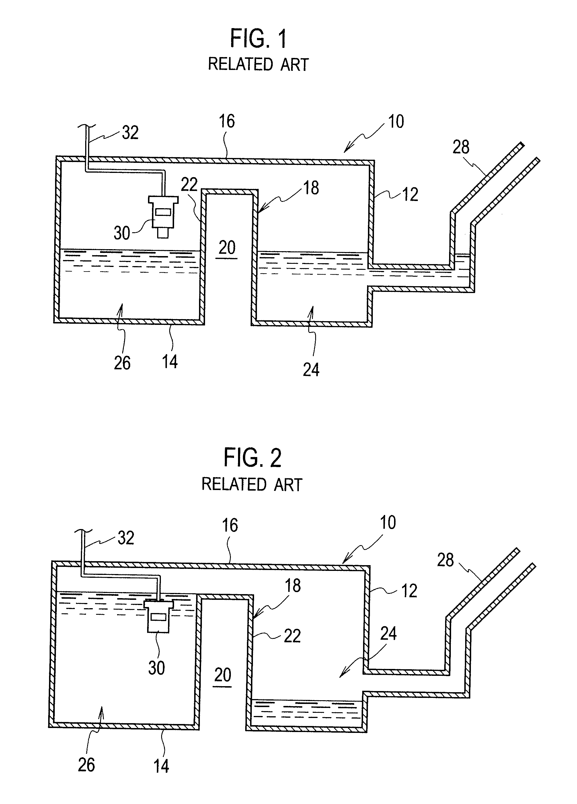
It will further be noted that differences in level between the sumps can give rise to problems when refueling the motor vehicle, particularly when the fuel in one sump of the tank reaches a level at which a refueling vent valve provided therein responds, although the maximum filling level has not yet been reached in the other sump.
In this case, the automatic shut-off valve in refueling gun shuts off prematurely in the refueling procedure, with the consequence that the tank cannot be completely filled.
This problem can occur in particular if the riser provided in the tank is particularly pronounced and the refueling vent valve shut-off level is below the level of the top of the riser, so that equalization of the levels in the sumps by fuel flowing across one sump into the other sump through a compensating or equalizing line could occur only after the refueling vent valve has responded.
It will be noted however that this involves ensuring the same filling level in different volumes of the sumps of the tank, both when the motor vehicle is stationary and also when it is in operation, although that may not always be desirable.
This design is disadvantageous however insofar as an identical level of fuel in each of the sumps of the tank is guaranteed only if the vehicle is not transversely inclined.
If the vehicle is transversely inclined when the tank is being refilled, it is still not possible to ensure that the automatic shut-off valve in the refueling gun shuts off when the level of fuel in the sumps is the same.
Such a design configuration suffers from disadvantages in terms of refueling.
As a result, the fuel tank 10 cannot be completely filled.

Method used


Image

  • Fuel tank
  • Fuel tank
  • Fuel tank

Examples


Embodiment Construction

[0035]Referring now to the drawings, FIGS. 3 through 7 depict a preferred embodiment according to the present invention.

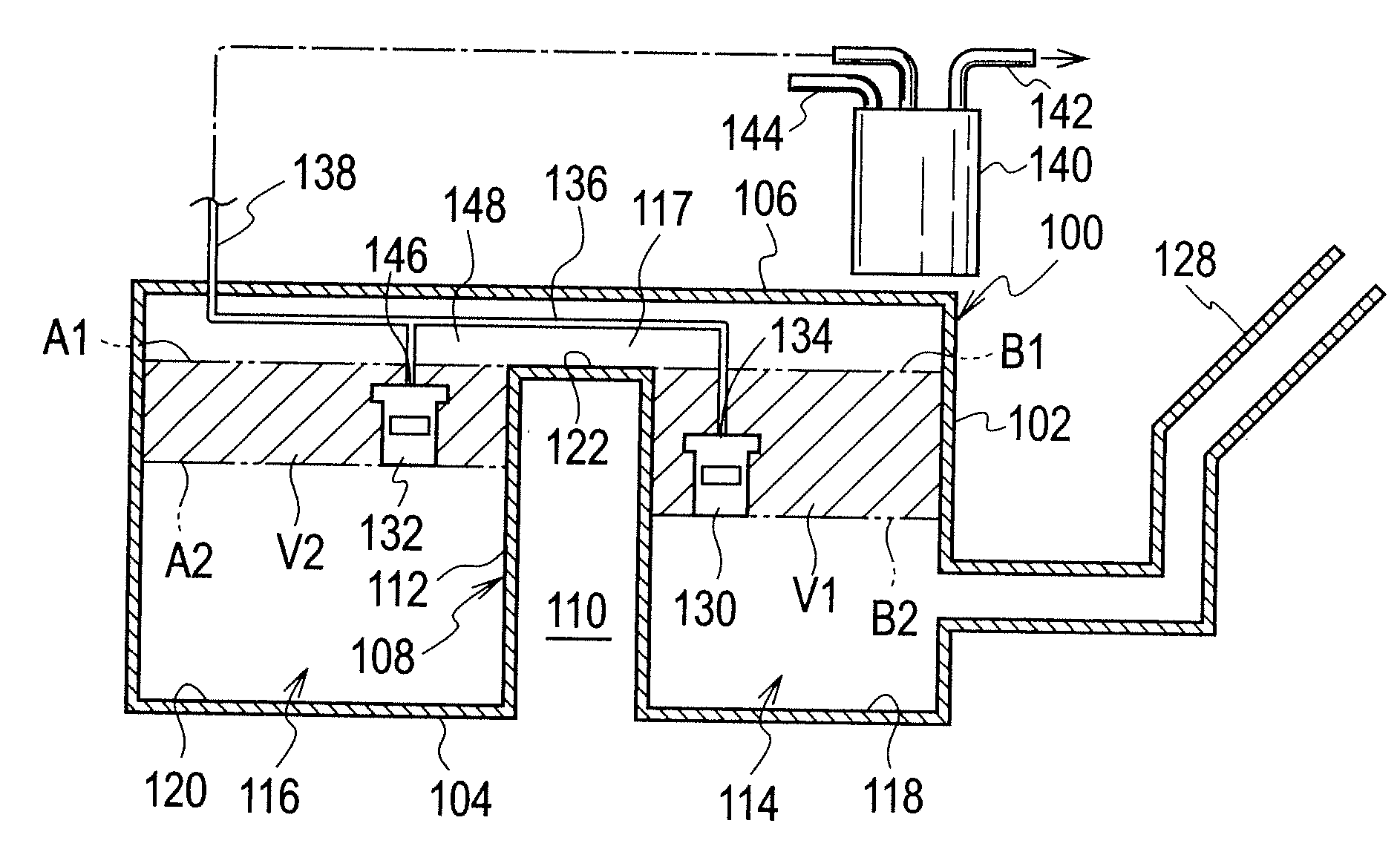
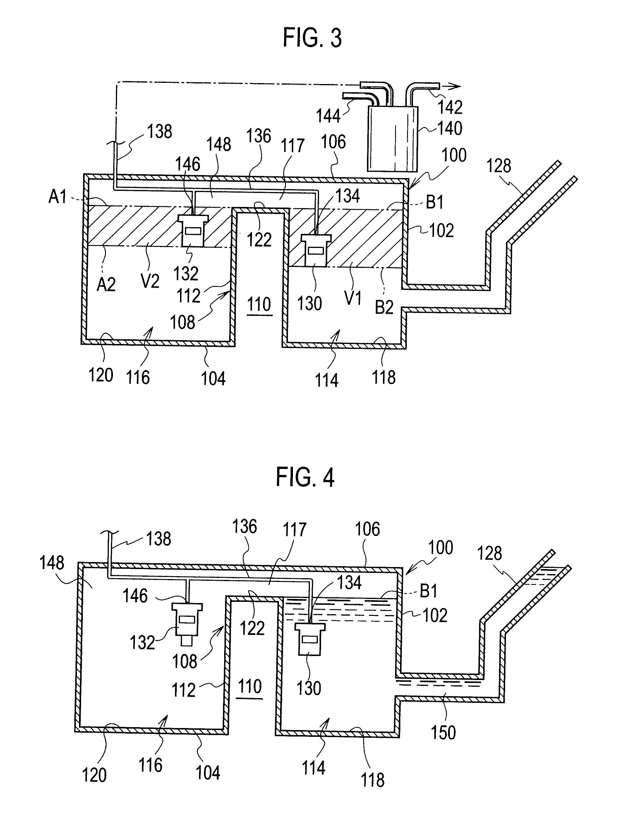
[0036]Each of FIGS. 3 through 7 depicts a sectional schematic view of a saddle fuel tank 100 having a tank shell 102. The tank shell 102 defines a bottom 104 and an oppositely disposed top 106. A bight 108 at the bottom 104 provides a concavity 110 exterior to the fuel tank 100 and a riser 112 interior to the fuel tank 100, in turn providing a primary sump 114 and a secondary sump 116. The primary and secondary sump 114 and 116 conjoin in a space 117 higher than the top of the riser 112. The bottom 104 is configured to a plurality of different levels. The interior wall of the bottom 104 is formed in a first level 118, a second level 120 spaced from the first level 118 and a third or highest level 122. The third level 122 interconnects the first level 118 and the second level 120, forming the riser 112 between the first and second levels 118 and 120. The first and s...


PUM

PropertyMeasurementUnit
volumeaaaaaaaaaa
heightaaaaaaaaaa
transverse acceleration forcesaaaaaaaaaa

Abstract

A fuel tank has a primary sump and secondary sump. A first vent valve and a second vent valve are disposed within the fuel tank. The first vent valve is closed when a level of fuel in the primary sump is equal to or higher than a first predetermined filling level, and the second vent valve is closed when a level of fuel in the secondary sump is equal to or higher than a second predetermined filling level in a refueling procedure.

Description

[0001]This application claims the priority based on Japanese Patent Application No. 2007-257707 filed Oct. 1, 2007, the content of which is hereby incorporated by reference.BACKGROUND OF THE INVENTION[0002]1. Field of the Invention[0003]The present invention relates to fuel tanks, and more particularly to automotive saddle fuel tanks. Still more particularly, the present invention relates to systems for controlling filling of a fuel tank in a refueling procedure.[0004]2. Background Art[0005]Automotive saddle fuel tanks have a tank shell defining a bottom. The tank shell is configured with a centrally disposed bight in the bottom thereof. The bight provides an exterior concavity which is intended to provide accommodation for drive and / or exhaust components of the vehicle to pass freely therethrough. While providing free space at the exterior of the fuel tank, the bight also provides a riser interior to the fuel tank, in turn providing two sumps, namely, a primary sump and a secondary...

Claims


Application Information

Patent Timeline
Patent Type & Authority Applications(United States)
IPC IPC(8): B60K15/077B60K15/035
CPCB60K15/03519B60K2015/03576B60K2015/03118F02M37/0094Y10T137/86324Y10T137/86212Y10T137/86075Y10T137/2842Y10T137/2877B60K15/03B60K15/077B60K15/035
Inventor CHINO, MINORUTANIMURA, NAOAKIKAMEI, MASASHIHANAI, JUNICHI
Owner NISSAN MOTOR CO LTD
Learn More