Method for Designing Spectacle Lens, and Spectacles

a technology of spectacle lens and design method, applied in the field of spectacle lens design, can solve the problems of average dioptric power error, astigmatic aberration, and concave surface of optical lens to form inappropriate angle with respect to spectacle frame, and achieve the effect of less likely to cause an error

Active Publication Date: 2009-04-02
HOYA LENS MFG PHILIPPINES
View PDF9 Cites 3 Cited by
  • Summary
  • Abstract
  • Description
  • Claims
  • Application Information

AI Technical Summary

Benefits of technology

[0013]An advantage of some aspects of the invention is to provide: a method for designing a spectacle lens that is less likely to cause an error irrespective of prescription made on an optical concave portion on an eye side; and spectacles.
[0017]Accordingly, unfavorable tilt of the optical concave surface can be prevented by setting the lens tilt angle θ, so that the spectacle lens can be mounted in the spectacle frame with the optical concave surface being in the appropriate angle irrespective of prescription for near-sightedness, far-sightedness or the like. Therefore, the average dioptric power error, the astigmatic aberration, and a prismatic error are reduced to prevent eyestrain or the like suffered by a spectacle user.
[0019]With the above arrangement, the average dioptric power error, the astigmatic aberration, and the prismatic error can be further reduced.
[0021]With the above arrangement, since parameters for defining the lens tilt angle θ are determined independently of the shape of the optical concave surface that differs from one prescription to another, the lens tilt angle θ is easily obtained.
[0026]Accordingly, the tilt of the optical concave surface can be obtained by calculation using the aforementioned parameters irrespective of the prescription, so that more accurate lens tilt angle θ can be determined.

Problems solved by technology

Thus, a prescription made on the optical concave surface on an eye side may cause the optical concave surface to form an inappropriate angle with respect to the spectacle frame.
When the optical concave surface tilts relative to the appropriate angle, an average dioptric power error, an astigmatic aberration, and a prismatic error occur.
A user may suffer eyestrain or the like due to such errors.

Method used


Image

  • Method for Designing Spectacle Lens, and Spectacles
  • Method for Designing Spectacle Lens, and Spectacles
  • Method for Designing Spectacle Lens, and Spectacles

Examples


Embodiment Construction

)

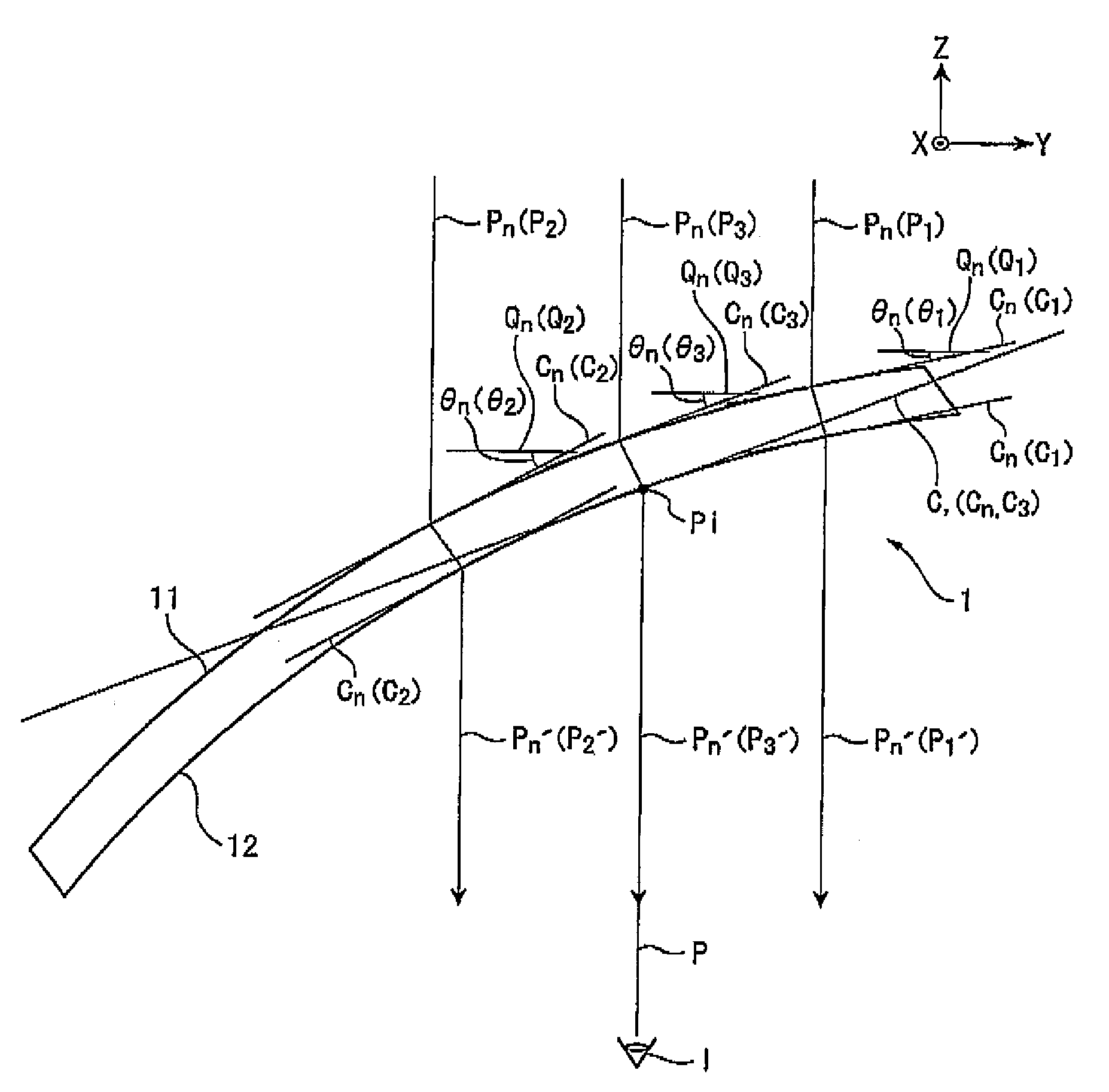
[0034]A method for designing a spectacle lens according to an exemplary embodiment of the invention will be described below with reference to the drawings.

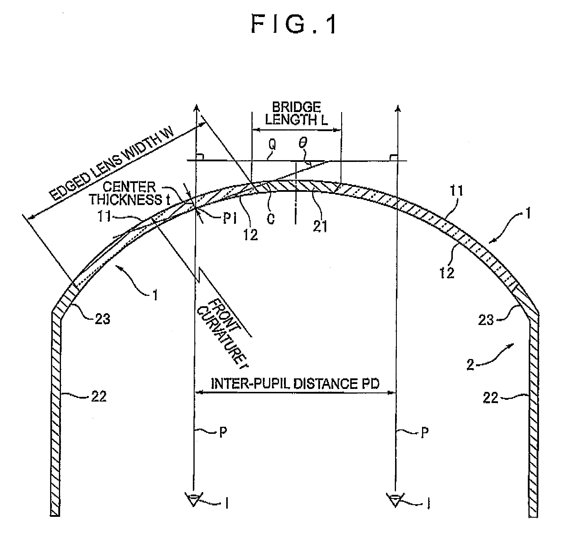
[0035]FIG. 1 is a schematic horizontal cross section of the spectacle according to the exemplary embodiment.

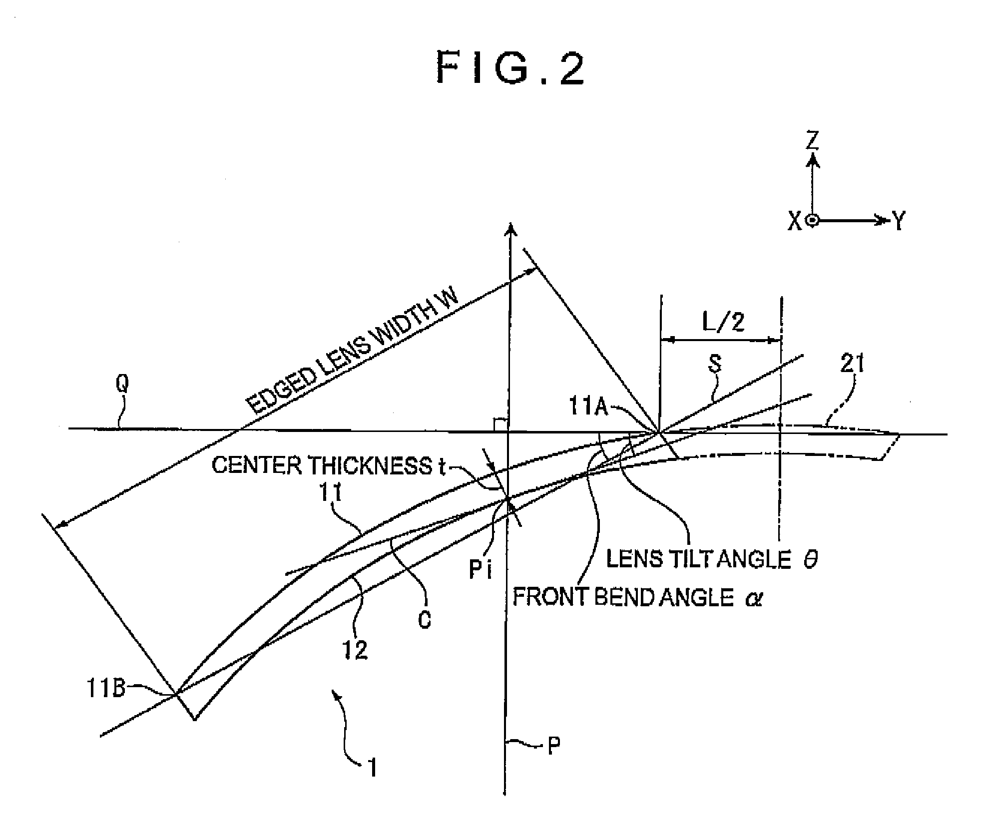
[0036]In FIG. 1, spectacles are provided with two spectacle lenses 1, each of which is mounted in the spectacle frame 2 in a manner tilting with respect to a forward sight line P.

[0037]The spectacle lens 1 is a meniscus lens having an optical convex surface 11 on an object side and an optical concave surface 12 on an eye side. The spectacle lens 1 is shaped in a sphere, and a radius of curvature, that is, a front curvature r, of the optical convex surface 11 has a predetermined dimension.

[0038]The spectacle frame 2 is a spectacle frame having a bend angle of 200° or larger such as a wraparound type spectacle frame or the like. A bridge 21 whose front side is substantially spherically curved and with which the spectacle is s...


PUM


Abstract

A method for designing a spectacle lens that includes an optical convex surface on an object side of the spectacle lens and an optical concave surface on an eye side of the spectacle lens and is mounted in a spectacle frame in a manner tilting with respect to a forward sight line, the optical convex surface being spherical, the optical concave surface being optically curved according to a prescription, the method including: defining a design reference point at an intersection of the optical concave surface and the forward sight line; and determining an angle formed by a tangent line at the design reference point and a perpendicular plane perpendicular to the forward sight line as a lens tilt angle θ with which the spectacle lens is mounted in the spectacle frame.

Description

[0001]The entire disclosure of Japanese Patent Application No. 2007-254293, filed Sep. 28, 2007 and No. 2008-173311, filed Jul. 2, 2008 is expressly incorporated by reference herein.BACKGROUND[0002]1. Technical Field[0003]The present invention relates to a method for designing a spectacle lens to be mounted in a spectacle frame having a large bend angle such as a wraparound type spectacle frame.[0004]2. Related Art[0005]In recent years, a spectacle frame of the wraparound type has become popular, especially as sports sunglasses. The spectacle frame of the wraparound type has a characteristic that, since the spectacle frame of the wraparound type has a large bend angle to bend around a face, even the sides of the face are covered by lenses and the field of view is wide. Therefore, a spectacle frame of the wraparound type is popular among athletes as a frame for safety spectacles used during sports and for general eye protection.[0006]The wraparound type spectacle lens is provided wit...

Claims


Application Information

Patent Timeline
Patent Type & Authority Applications(United States)
IPC IPC(8): G02C7/02
CPCG02C13/005G02C7/02
Inventor ITO, AYUMUKAGA, TADASHI
Owner HOYA LENS MFG PHILIPPINES
Why Eureka
Try Eureka