
System-on-chip communication manager

a communication manager and system-on-chip technology, applied in the field of system and method for managing communications between processors, can solve the problems of increasing the communication load within the soc, both in complexity and throughpu

Inactive Publication Date: 2009-04-02
MACOM CONNECTIVITY SOLUTIONS LLC
View PDF6 Cites 19 Cited by
  • Summary
  • Abstract
  • Description
  • Claims
  • Application Information

AI Technical Summary

Benefits of technology

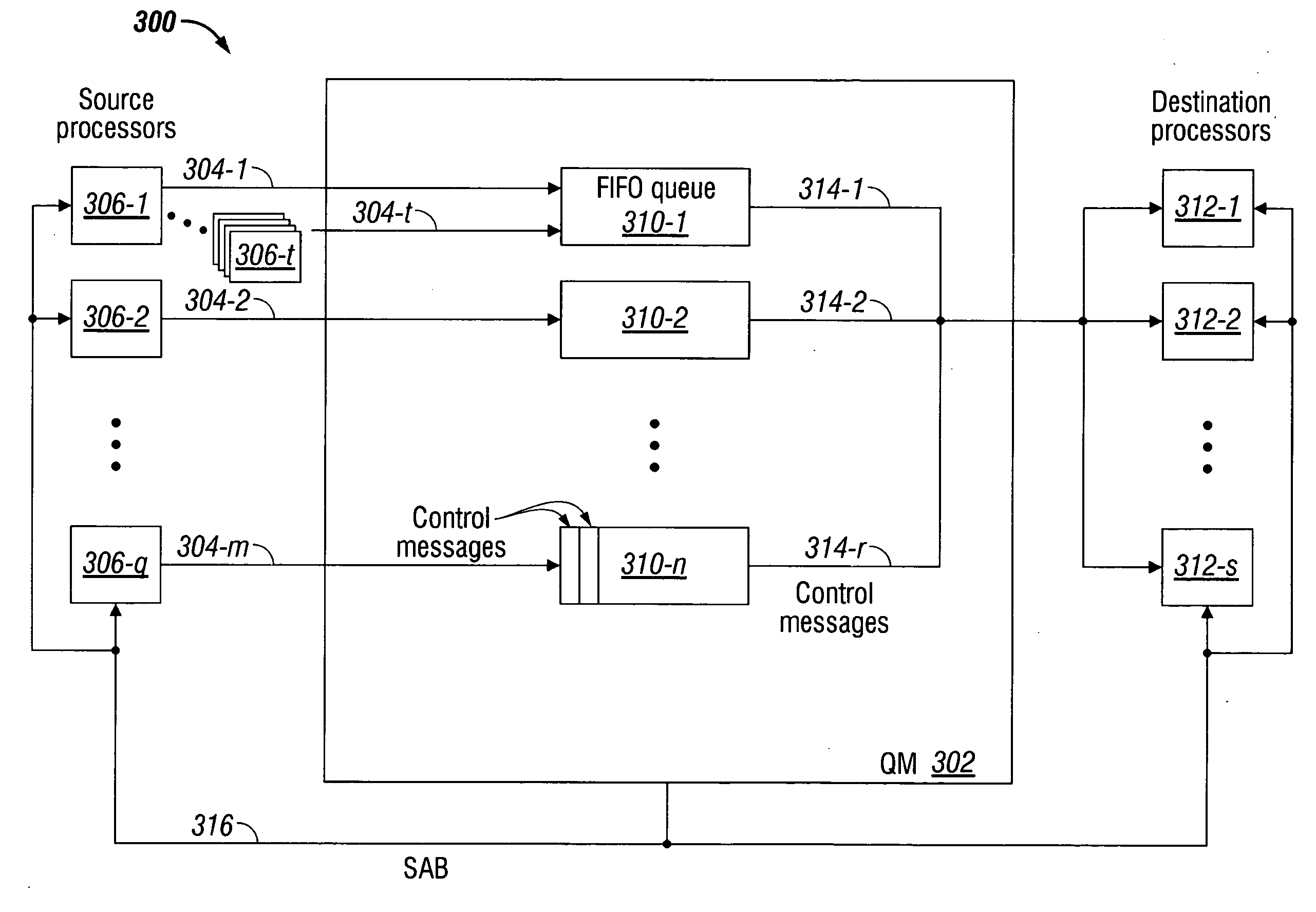
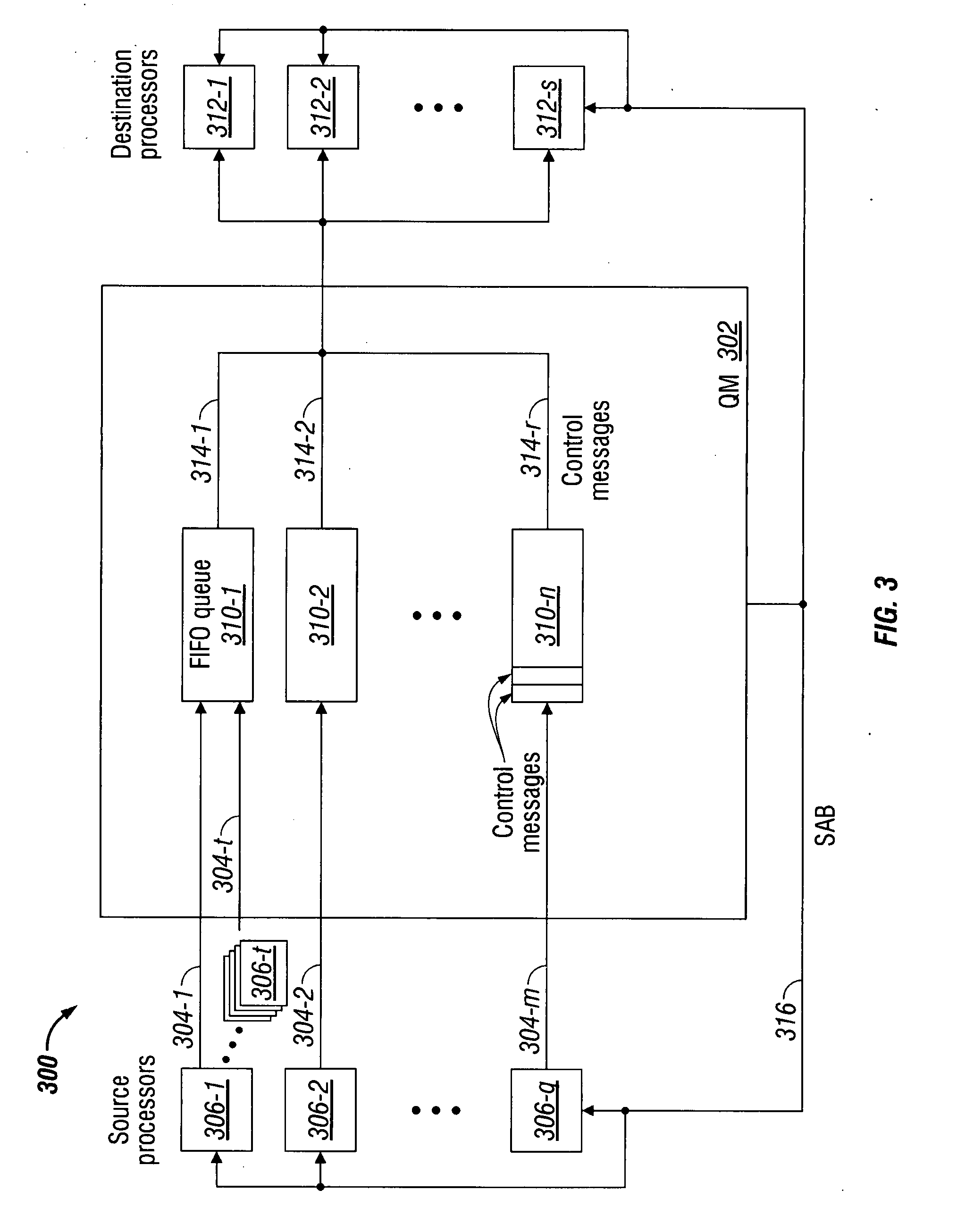
[0011]Accordingly, a method is provided for communicating control messages between processors. The method accepts control messages from a source processor addressed to a destination processor. The control messages are loaded in a first-in first-out (FIFO) queue associated with the destination processor. Then, the method serially supplies loaded control messages to the destination processor from the queue.
[0012]The messages may be accepted from a plurality of source processors addressed to the same destination processor. The control messages are added to the queue in the order in which they are received. In one aspect, a plurality of parallel FIFO queues may be established that are associated with the same destination processor. Then, the method differentiates the control messages into the parallel FIFO queues and supplies control messages from the parallel FIFO queues in an order responsive to criteria such as queue ranking, weighting, or shaping. Alternately, queue selection instructions may be received from the destination processor, and control messages are supplied from a selected FIFO queue in response to the queue selection instructions.
[0013]More explicitly, the loading of control messages in the FIFO queue includes writing messages from the source processor into a memory associated with a FIFO q...

Problems solved by technology

These advancements increase the communications load within the SoC, both in complexity and throughput.

Method used


Image

  • System-on-chip communication manager
  • System-on-chip communication manager
  • System-on-chip communication manager

Examples


Embodiment Construction

[0028]Various embodiments are now described with reference to the drawings. In the following description, for purposes of explanation, numerous specific details are set forth in order to provide a thorough understanding of one or more aspects. It may be evident, however, that such embodiment(s) may be practiced without these specific details. In other instances, well-known structures and devices are shown in block diagram form in order to facilitate describing these embodiments.

[0029]As used in this application, the terms “processor”, “processing. device”, “component,”“module,”“system,” and the like are intended to refer to a computer-related entity, either hardware, firmware, a combination of hardware and software, software, or software in execution. For example, a component may be, but is not limited to being, a process running on a processor, generation, a processor, an object, an executable, a thread of execution, a program, and / or a computer. By way of illustration, both an app...


PUM


Abstract

A Queue Manager (QM) system and method are provided for communicating control messages between processors. The method accepts control messages from a source processor addressed to a destination processor. The control messages are loaded in a first-in first-out (FIFO) queue associated with the destination processor. Then, the method serially supplies loaded control messages to the destination processor from the queue. The messages may be accepted from a plurality of source processors addressed to the same destination processor. The control messages are added to the queue in the order in which they are received. In one aspect, a plurality of parallel FIFO queues may be established that are associated with the same destination processor. Then, the method differentiates the control messages into the parallel FIFO queues and supplies control messages from the parallel FIFO queues in an order responsive to criteria such as queue ranking, weighting, or shaping.

Description

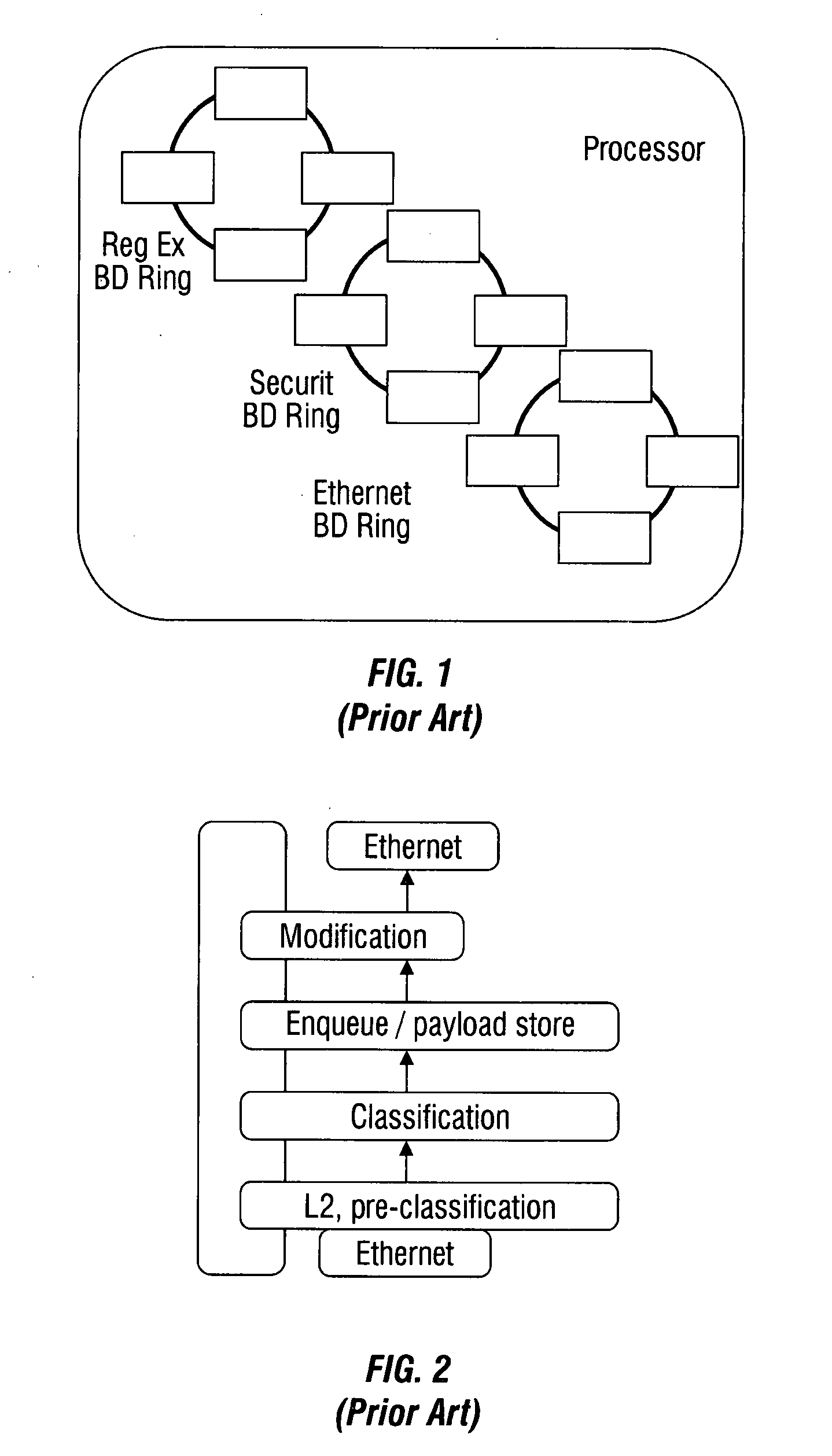
BACKGROUND OF THE INVENTION[0001]1. Field of the Invention[0002]This invention generally relates to digital processing devices and, more particularly, to a system and method for managing communications between processors.[0003]2. Description of the Related Art[0004]FIG. 1 is a schematic diagram depicting a processor employing buffer descriptor rings (prior art). Conventionally, communication between masters (e.g. processors and coprocessors) within a general purpose processor is enabled through the use of buffer descriptor rings. Shown is a processor with regular expressions (reg ex), security, and Ethernet buffer descriptor (BD) rings. A separate ring structure is provided for each to enable a one-to-one communication path within the system-on-chip (SoC). Each ring has a set of buffer descriptors and control mechanisms dedicated to the communication path between one producer (source processor) and one consumer (destination processor). Extensive software overhead is required to mana...

Claims


Application Information

Patent Timeline
IPC IPC(8): H04L12/56
CPCH04L49/90H04L49/9047H04L49/901
Inventor FAIRHURST, MARKDICKEY, JOHN
Owner MACOM CONNECTIVITY SOLUTIONS LLC
Learn More