Piping having fluid-mixing region
a fluid-mixing region and fluid-mixing technology, applied in the field of pipes, can solve the problems of difficult to completely prevent the variations of temperature interfaces occurring at various sites of the piping, and achieve the effects of preventing thermal fatigue, facilitating fluid mixing, and reducing temperature variations
- Summary
- Abstract
- Description
- Claims
- Application Information
AI Technical Summary
Benefits of technology
Problems solved by technology
Method used
Image

Examples
first embodiment
[0085]A first embodiment of the present invention will now be described with reference to FIG. 1.
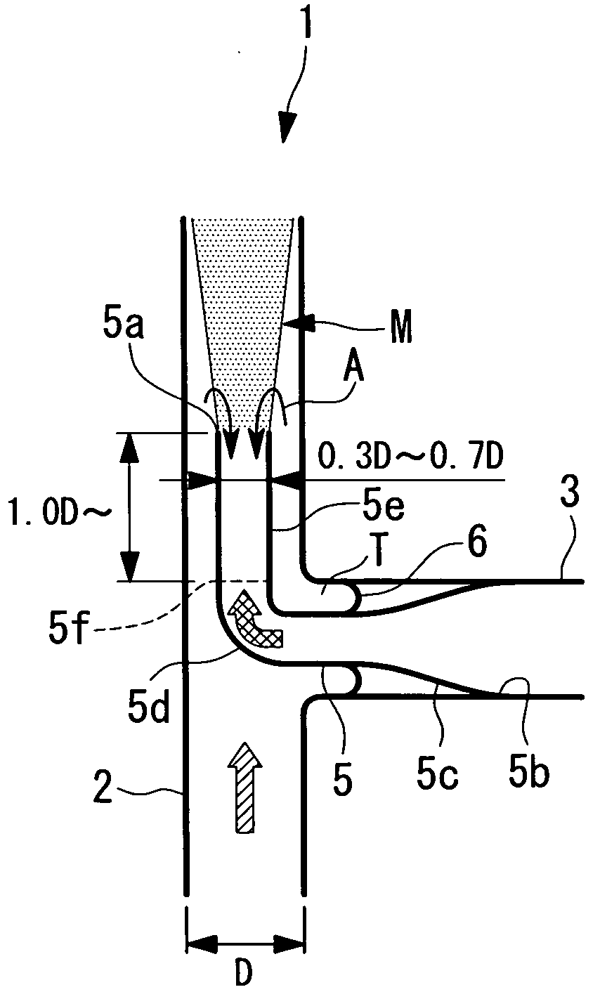
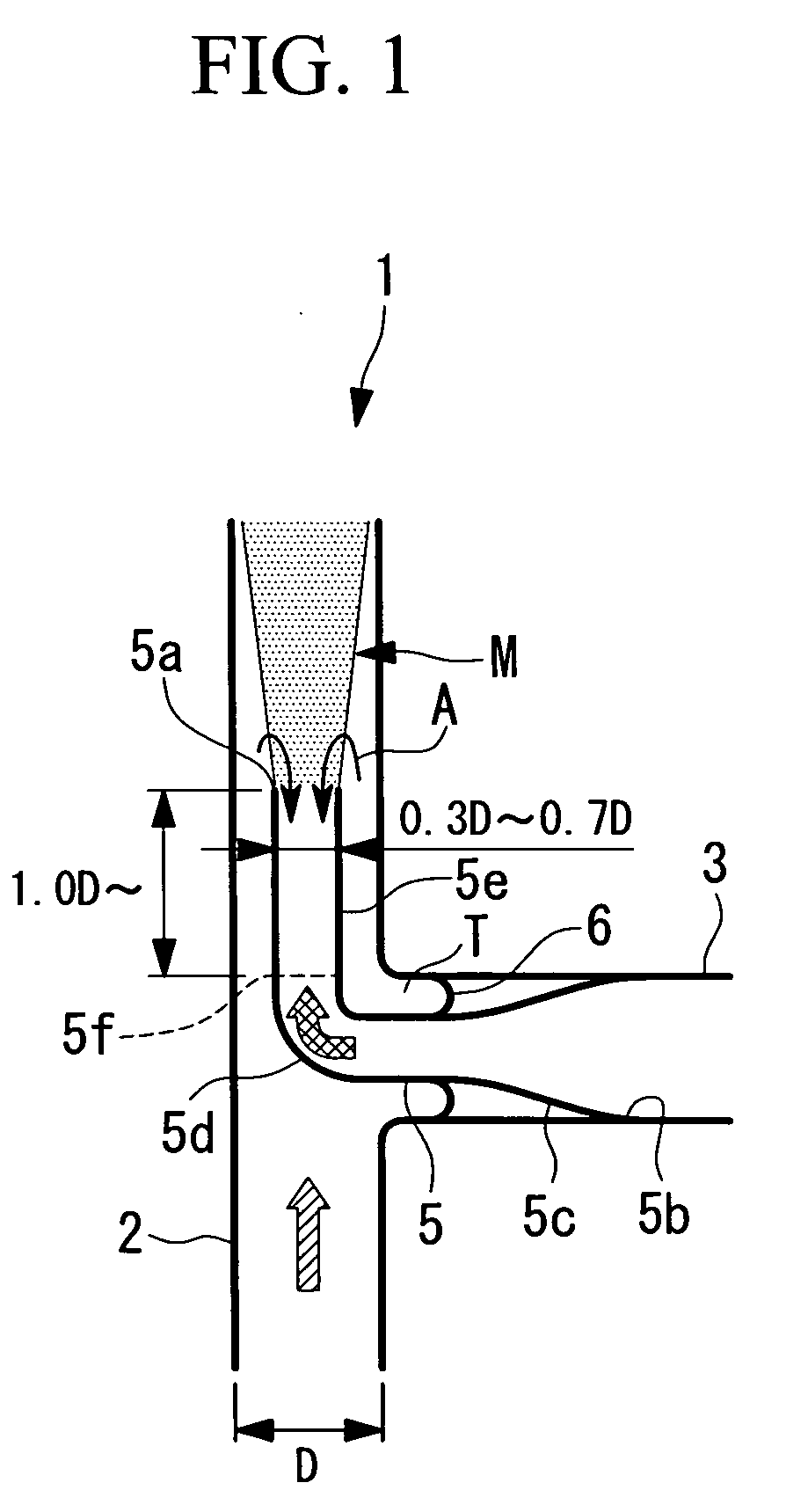
[0086]FIG. 1 shows piping 1 having a fluid-mixing region M.
[0087]The piping 1 includes a main pipe (first pipe) 2 and a branch pipe (second pipe) 3.
[0088]The main pipe 2 has an inner diameter D and is formed of metal. In FIG. 1, high-temperature water (high-temperature fluid) flows from bottom to top.
[0089]The branch pipe 3 is connected to an outer wall of the main pipe 2 perpendicularly. The branch pipe 3 is formed of metal, and low-temperature water (low-temperature fluid) having a lower temperature than the high-temperature water flowing through the main pipe 2 flows through the branch pipe 3. In FIG. 1, the low-temperature water flows from right to left in the branch pipe 3, passes through a reducer (inner pipe) 5, and flows into the main pipe 2 through a downstream end 5a of the reducer S.
[0090]An upstream end 5b of the reducer 5 is fixed to an inner wall of the branch pipe 3. The r...
second embodiment
[0106]Next, a second embodiment of the present invention will now be described with reference to FIG. 3.
[0107]This embodiment differs from the first embodiment in that a small-diameter portion 5g is provided at the end portion 5e of the reducer 5, and the other features are identical. Hence, the identical portions will not be described.
[0108]Referring to FIG. 3, the small-diameter portion 5g is provided on the downstream side of the end portion 5e of the reducer 5 and has a smaller inner diameter than the upstream side thereof. The small-diameter portion 5g further accelerates the low-temperature water flowing through the branch pipe 3 and guided into the reducer 5. This prevents the high-temperature water flowing along the outside of the reducer 5 from flowing back into the reducer 5. Thus, no temperature interface reaches a deep level inside the reducer 5, so that the possibility of breakage at the weld line 5f′ due to thermal fatigue is eliminated.
[0109]FIG. 4 shows a modificatio...
third embodiment
[0111]Next, a third embodiment of the present invention will now be described with reference to FIG. 5.
[0112]This embodiment differs from the first embodiment in that an inner cylinder 10 is provided at the end of the reducer 5, and the other features are identical. Hence, the identical portions will not be described.
[0113]Referring to FIG. 5, the inner cylinder 10 is inserted in the end portion 5e of the reducer 5. A downstream end 10a of the inner cylinder 10 is disposed downstream of the downstream end 5a of the reducer 5. A gap having an annular cross section is formed between the outer circumferential wall of the inner cylinder 10 and the inner circumferential wall of the end portion 5e of the reducer 5.
[0114]In this embodiment, because the inner cylinder 10 is disposed in the reducer 5 with the gap formed between the inner circumferential wall of the reducer 5 and the outer circumferential wall of the inner cylinder 10, the low-temperature water flowing through the reducer 5 i...
PUM
 Abstract
Description
Claims
Application Information
 - R&D
- Intellectual Property
- Life Sciences
- Materials
- Tech Scout
- Unparalleled Data Quality
- Higher Quality Content
- 60% Fewer Hallucinations
Browse by: Latest US Patents, China's latest patents, Technical Efficacy Thesaurus, Application Domain, Technology Topic, Popular Technical Reports.
© 2025 PatSnap. All rights reserved.Legal|Privacy policy|Modern Slavery Act Transparency Statement|Sitemap|About US| Contact US: help@patsnap.com