Liner Drilling Method and Liner Hanger

Active Publication Date: 2009-04-09
SCHLUMBERGER TECH CORP
View PDF34 Cites 101 Cited by
  • Summary
  • Abstract
  • Description
  • Claims
  • Application Information

AI Technical Summary

Benefits of technology

[0009]In this invention, the operator makes up a liner string with a lower sub on bottom joint of the liner string and suspends the liner in the well at the rig floor. The operator makes up a string of drill pipe with a bottom hole assembly, which includes a drill bit on the lower end, and a telescoping sub having an adjustable length above the bottom hole assembly. The operator lowers the drill pipe, the bottom hole assembly and the telescoping sub into the liner and engages the bottom hole assembly with the lower sub such that torque may be transm

Problems solved by technology

If the operator wishes to retrieve the bottom hole assembly before cementing the liner, there are no established methods and equipment for doing so.
Also,

Method used


Image

  • Liner Drilling Method and Liner Hanger
  • Liner Drilling Method and Liner Hanger
  • Liner Drilling Method and Liner Hanger

Examples


Embodiment Construction

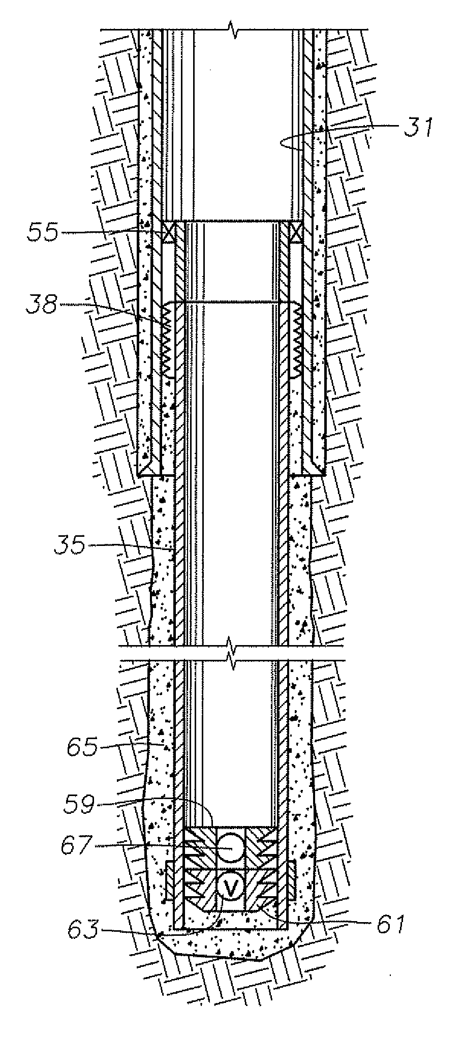
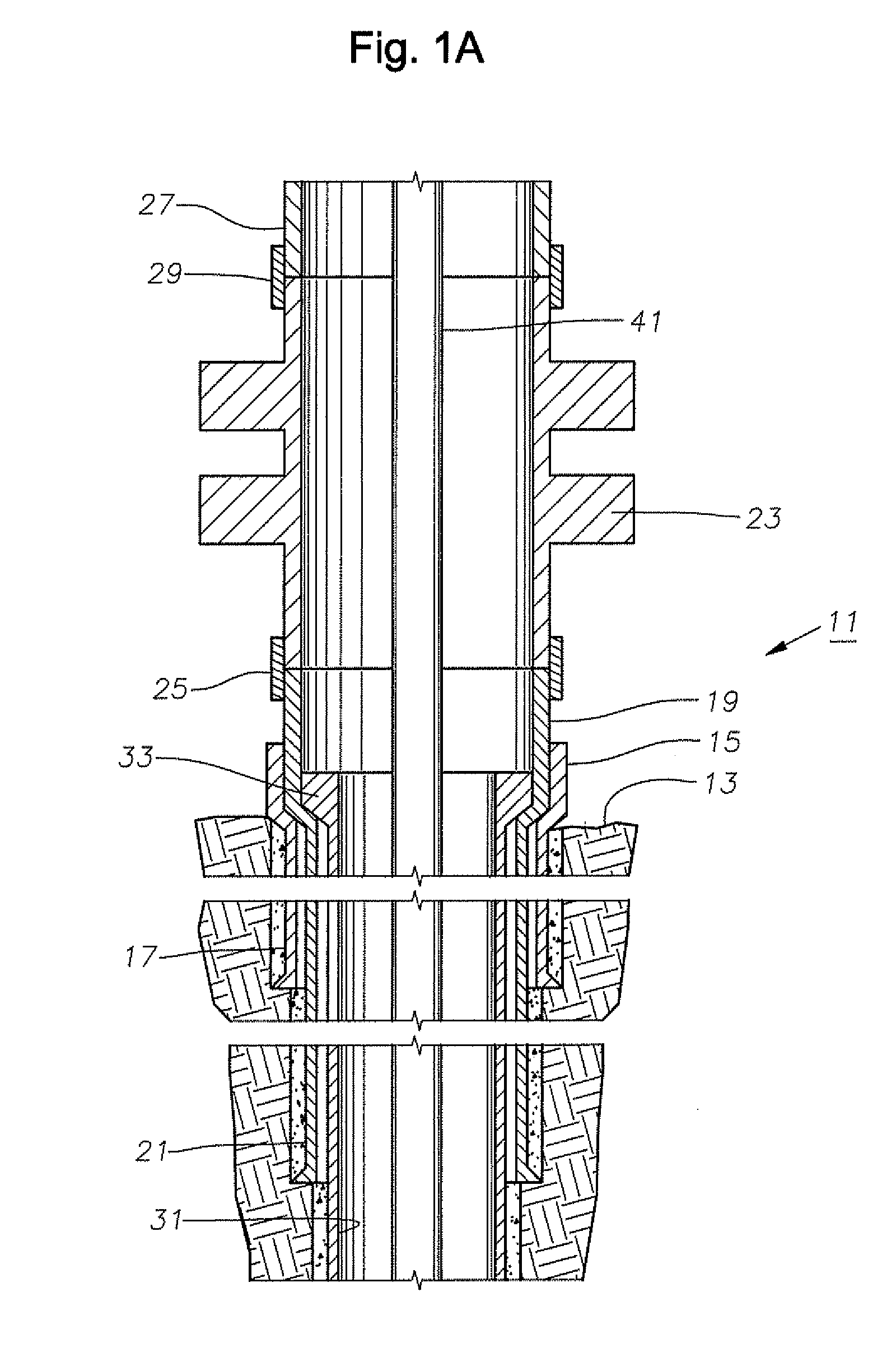
[0023]FIG. 1A shows a typical subsea wellhead assembly 11 during drilling. Subsea wellhead assembly 11 is at sea floor 13 and includes an outer wellhead housing 15 secured to a first string of casing or conductor pipe 17 that extends to a first depth in the well. An inner or high pressure wellhead housing 19 is shown landed in outer wellhead housing 15. Inner wellhead housing 19 is secured to a second string of casing 21 that extends to a second depth in the well.

[0024]A blowout preventer or lower marine riser package 23 is secured to the upper end of inner wellhead housing 19 by a connector 25. Blowout preventer 23 is connected to a drilling riser 27 that extends upward to a drilling platform, which may be floating or fixed. The drilling platform may have a riser tensioner system that maintains tension in riser 27. Riser 27 is connected to blowout preventer 23 by a connector 29.

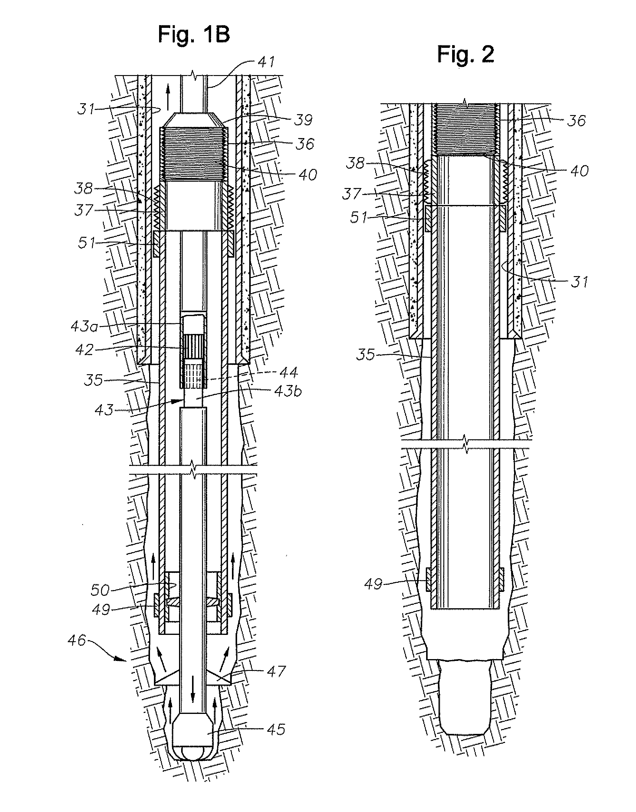
[0025]As illustrated in FIGS. 1A and 1B, the operator has drilled through inner wellhead housing 19 and c...


PUM


Abstract

An installation system for installing a liner in a well includes drilling while simultaneously running the liner. A string of drill pipe with a bottom hole assembly including a drill bit on a lower end is lowered into the liner while the liner is suspended at the rig floor. The bottom hole assembly engages a lower sub of the liner for torque transmission. A running tool secured to the drill pipe engages the upper sub such that the running tool supports the weight of the liner and transmits torque. The drill pipe and liner are rotated to drill deeper into the welbore. The liner hanger can be set to engage the casing, then released and reset at a different point.

Description

CROSS-REFERENCE TO RELATED APPLICATION[0001]This application claims priority to provisional patent application 60 / 977,263 filed Oct. 3, 2007.FIELD OF THE INVENTION[0002]This invention relates in general to oil and gas well drilling while simultaneously installing a liner in the well bore.BACKGROUND OF THE INVENTION[0003]Oil and gas wells are conventionally drilled by drilling with drill pipe to a certain depth, then running and cementing casing in the well. The operator may then drill the well to a greater depth with drill pipe and cementing another string of casing. In this type of system, each string of casing extends to the surface wellhead assembly, whether on land or subsea.[0004]In some wells, an operator may install a liner rather than an inner string of casing. The liner is made up of joints of pipe in the same manner as casing. Also, the liner is cemented into the well, normally. However, a liner does not extend back to the wellhead assembly at the surface. Instead, it is s...

Claims


Application Information

Patent Timeline
IPC IPC(8): E21B33/14E21B7/20
CPCE21B7/20E21B33/14E21B33/04E21B10/64
Inventor BROUSE, MICHAEL
Owner SCHLUMBERGER TECH CORP
Why Eureka
Try Eureka