
Cutting tool holder and a cutting insert therefor

Active Publication Date: 2009-04-09
NO SCREW
View PDF9 Cites 21 Cited by
  • Summary
  • Abstract
  • Description
  • Claims
  • Application Information

AI Technical Summary

Benefits of technology

[0005]An object of the present invention is to provide a cutting tool, and a cutting insert therefor, which enable indexing of the cutting insert to be effected in a minimum of time and with a minimum of labor. Another object of the invention is to provide a cutting tool, and a cutting insert thereof, which do not require the use of a separate fastener to be inserted and removed in order to permit the mounting of the cutting insert onto the cutting tool, as well as attachment and detachment of the cutting insert during an indexing operation.

Problems solved by technology

The cutting edges of cutting tools wear rapidly when used for cutting operations, particularly when cutting hard materials such as metal, and therefore they must be frequently replaced or resharpened.
Each of these operations involves time and labor, and since cutting tools generally include a plurality of such cutting inserts, the time and labor costs involved in indexing the cutting inserts in a cutting tool are considerable.

Method used


Image

  • Cutting tool holder and a cutting insert therefor
  • Cutting tool holder and a cutting insert therefor
  • Cutting tool holder and a cutting insert therefor

Examples


Embodiment Construction

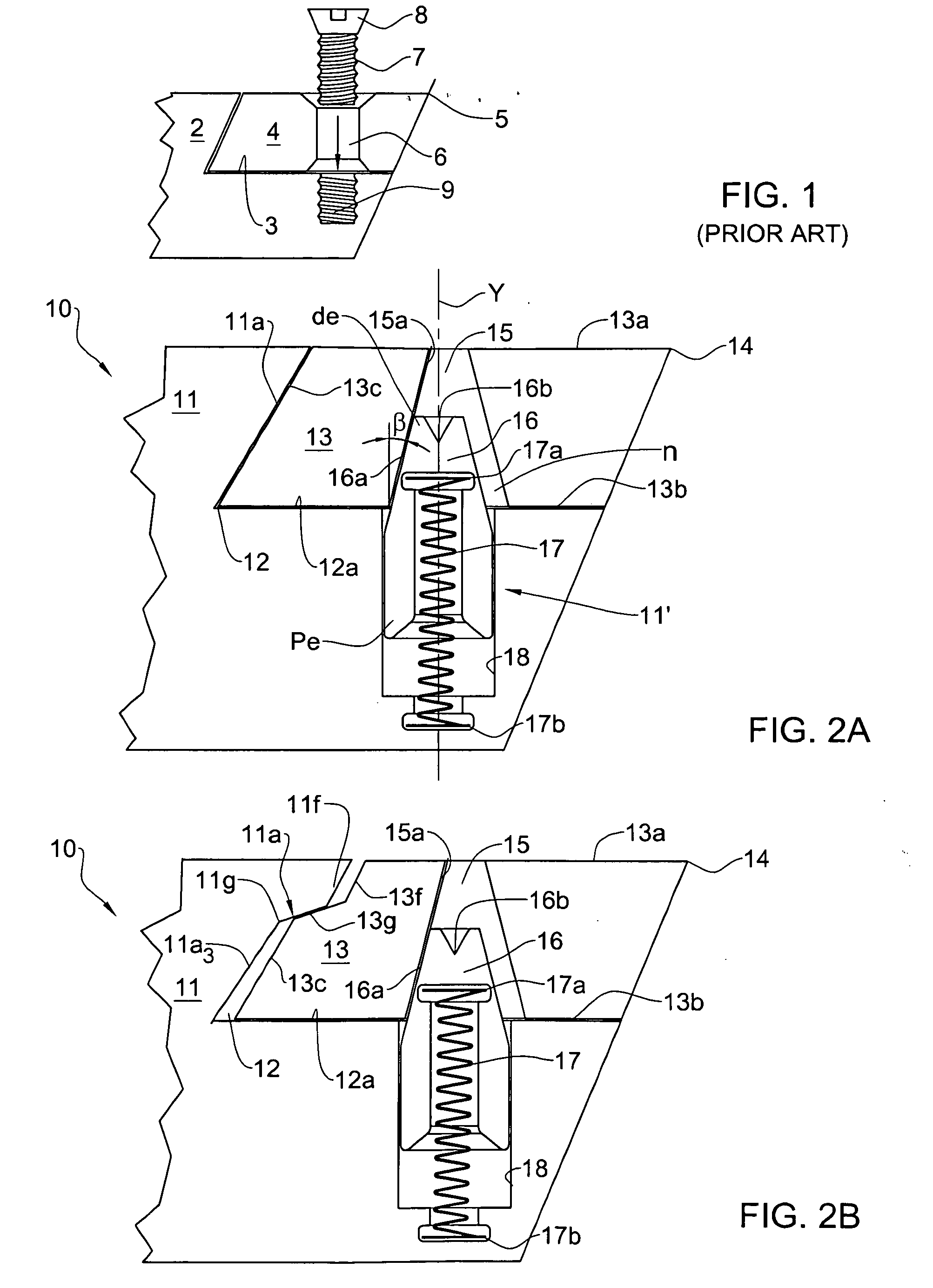
[0183]With reference to FIG. 1, a typical cutting tool according to the prior art is shown comprising a cutting tool holder and cutting insert. It is observed that the construction therein illustrated includes a cutting tool holder 2 formed with a seat 3 for receiving the cutting insert 4 having a plurality of cutting edges, one of which is shown at 5. The cutting insert 4 is further formed with a central bore 6 for receiving a threaded fastener 7 having an enlarged conical head 8. The fastener 7 is essentially a bolt inserted into and passed through bore 6 from its top side and threaded into a threaded socket 9 formed in the bottom surface of the seat 3.

[0184]It is observed that in such a prior art construction, each time the cutting insert 4 is to be mounted, dismounted, reversed or rotated to orient a fresh cutting edge 5 for a cutting operation, it is necessary to remove the fastener 7, remove the cutting insert 4, rotate it a partial rotation (e.g., 90° in a square cutting inse...


PUM


Abstract

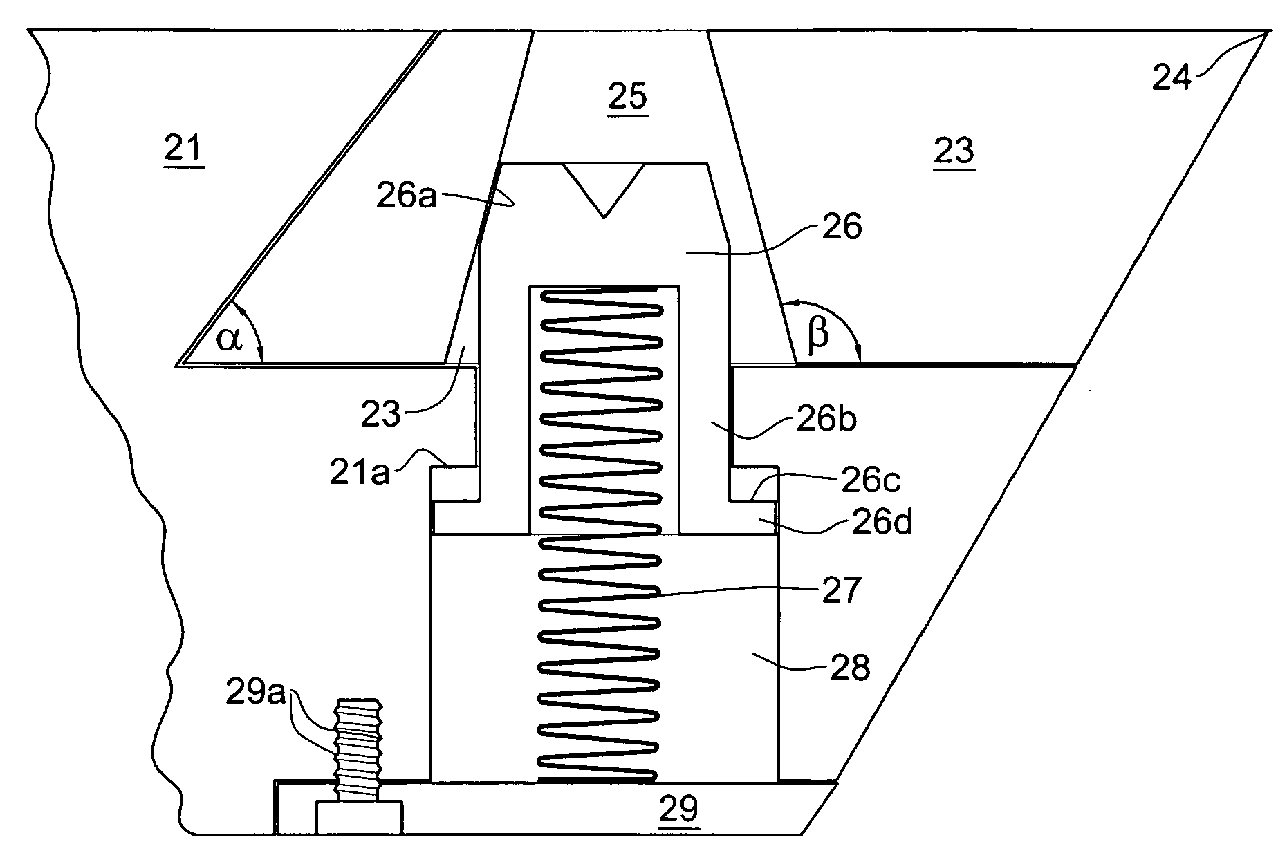
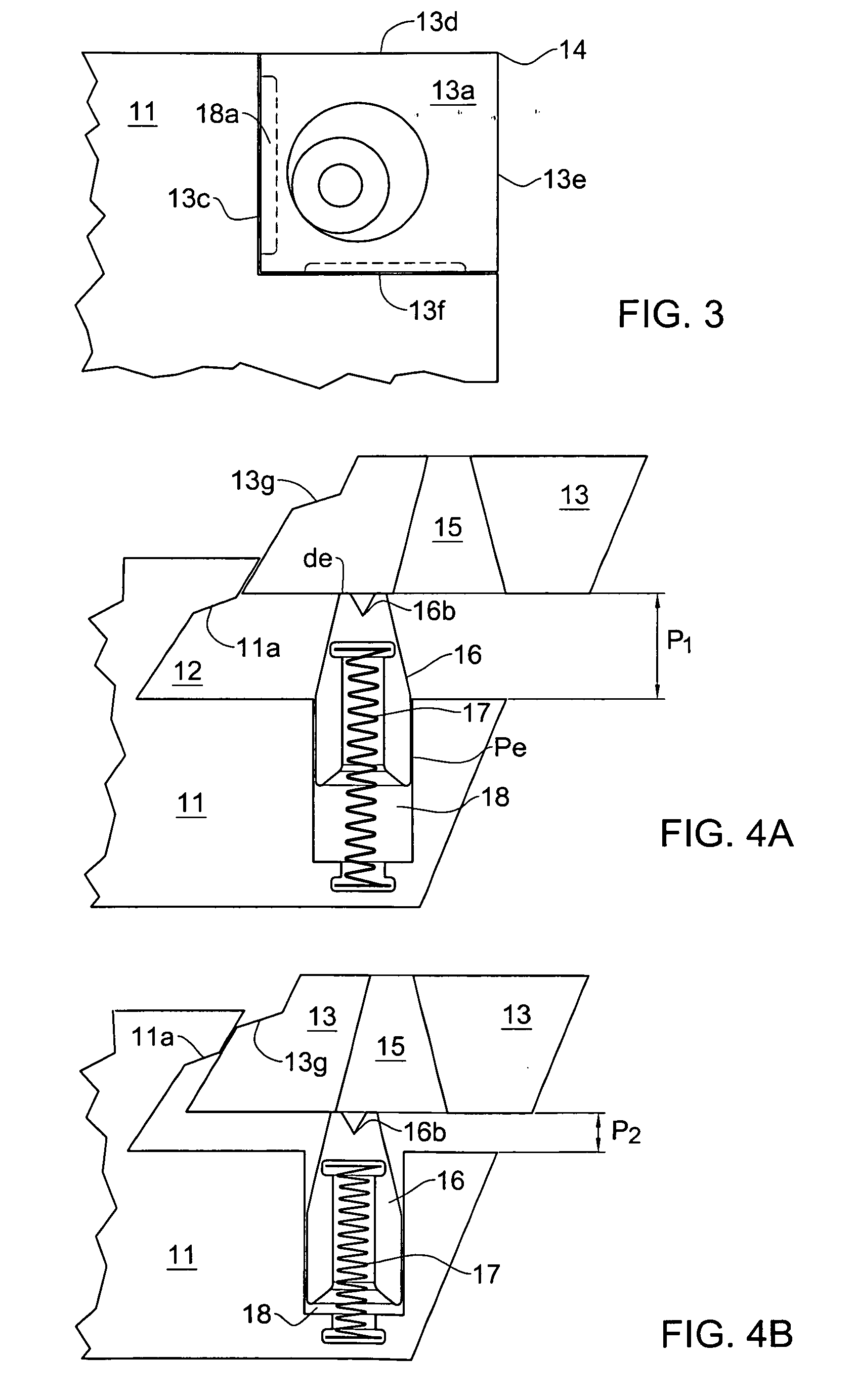
A cutting tool holder adapted for mounting thereon a cutting insert having a top face, a bottom face and formed with an insert bore having an inner surface extending between the top and the bottom face. The holder comprises a seat defined by a bottom surface and at least one side wall angled to the bottom surface, a seat bore with a bore axis having an open end at the bottom surface of the seat, and a securing mechanism for securing the cutting insert in the seat. The securing mechanism comprises a securing pin received within the seat bore and having a body with an outer surface extending between a proximal end and a distal end of the body and defining a pin axis therealong. The securing mechanism further comprises a displacement arrangement adapted for axially displacing the securing pin along the bore axis of the seat bore between at least a first, mounting position in which the distal end protrudes from within the seat bore through the bottom surface into the seat to a first extent so as to allow the cutting insert to be placed within the seat, having its bottom face aligned against the bottom surface, and a second, securing position in which the distal end protrudes from within the seat bore through the bottom surface into the seat to a second extent, greater than the first extent, so as to engage the inner surface of the insert bore, thereby securing the insert in place.

Description

[0001]This application is a Continuation-in-Part of International Application No. PCT / IL2008 / 000778 filed Jun. 5, 2008.FIELD OF THE INVENTION[0002]The present application relates variations and improvements in cutting tools, cutting tool holders and cutting inserts, in particular to securing arrangements for cutting inserts.BACKGROUND OF THE INVENTION[0003]The cutting edges of cutting tools wear rapidly when used for cutting operations, particularly when cutting hard materials such as metal, and therefore they must be frequently replaced or resharpened. In many types of cutter machines, such as milling machines, the cutting tool includes a plurality of such cutting edges formed in cutting inserts which are fixed within seats in the cutting tool. Each such cutting insert usually includes a plurality of cutting edges, which are sequentially oriented in cutting operations by indexing the cutting insert within the respective seat of the cutting tool.[0004]In the conventional cutting too...

Claims


Application Information

Patent Timeline
IPC IPC(8): B26D1/12B26D1/00
CPCB23B27/12Y10T407/23B23B29/03417B23B51/02B23B2200/0423B23B2200/123B23B2200/125B23B2200/128B23B2200/3618B23B2200/369B23B2205/04B23B2205/045B23B2205/08B23B2205/12B23B2251/02B23B2251/50B23B2260/0785B23B2260/136B23C5/2213B23C5/2221B23C2210/03B24B45/006F16B2/14F16D1/06Y10T407/191Y10T407/1906Y10T407/2274Y10T407/1934Y10T407/2272Y10T407/235Y10T29/53B23B27/1622
Inventor HARIF, GERSHON
Owner NO SCREW
Learn More