Method and Apparatus for Elimination of Spurious Response due to Mixer Feed-Through

a technology of mixer feed-through and spurious response, which is applied in the direction of digital variable/waveform display, instruments, measurement devices, etc., can solve the problem of degrading the specification of the oscilloscope with respect to the channel

Inactive Publication Date: 2009-04-09
TELEDYNE LECROY
View PDF20 Cites 8 Cited by
  • Summary
  • Abstract
  • Description
  • Claims
  • Application Information

AI Technical Summary

Benefits of technology

[0010]The invention accordingly comprises the several steps and the relation of one or more of such steps with respect to each of the others, and the apparatus embodying features of construction, combination(s) of elements and arrangement of parts that are adapted to effect such steps, all as exemplified in the following detailed disclosure, and the scope of the invention will be indicated in the claims.

Problems solved by technology

When the RF-IF isolation is not better than an SFDR specification of the oscilloscope individual channels, there may be a degradation of the specification of the oscilloscope with respect to the channels.

Method used


Image

  • Method and Apparatus for Elimination of Spurious Response due to Mixer Feed-Through
  • Method and Apparatus for Elimination of Spurious Response due to Mixer Feed-Through
  • Method and Apparatus for Elimination of Spurious Response due to Mixer Feed-Through

Examples


Embodiment Construction

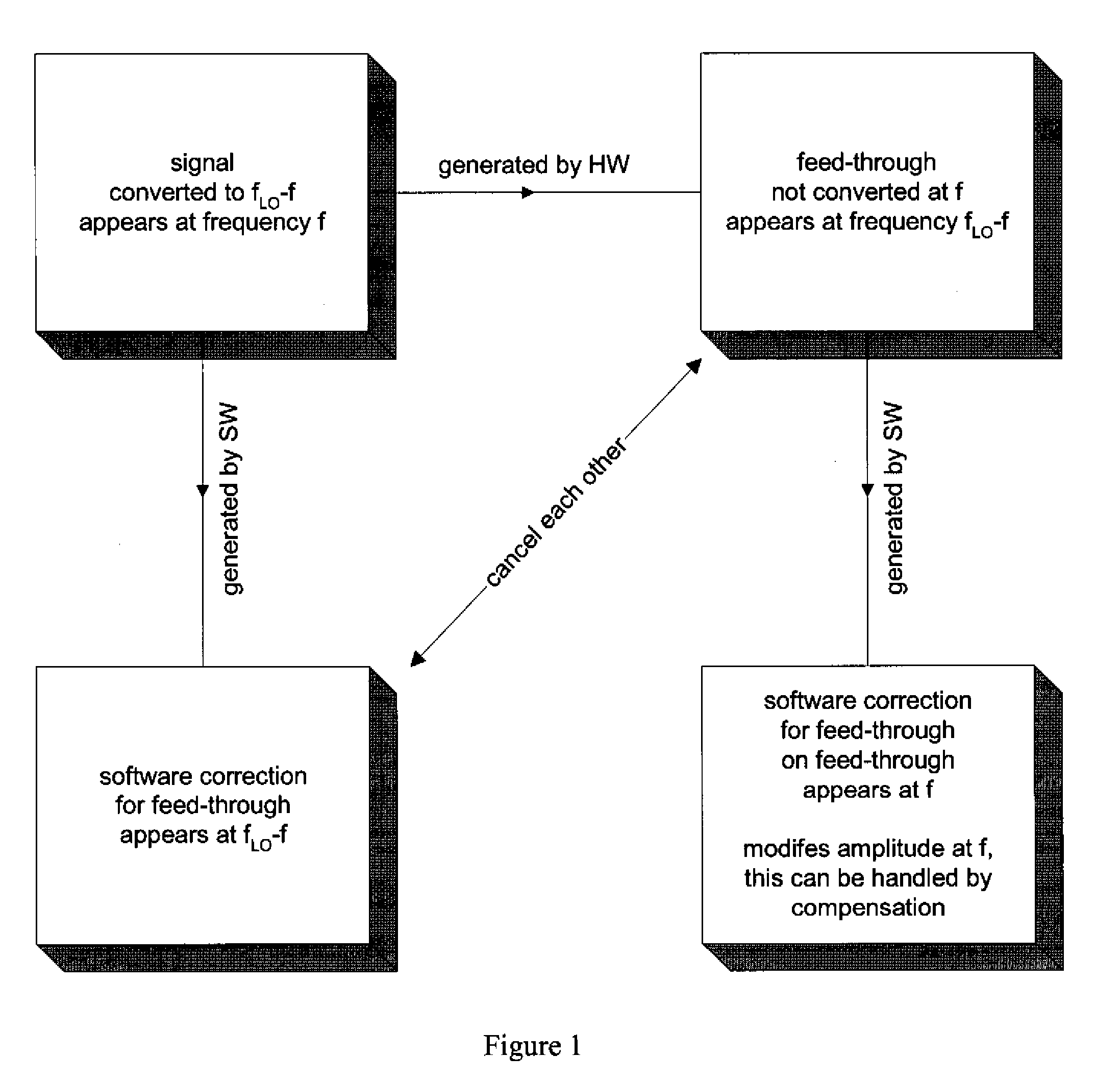
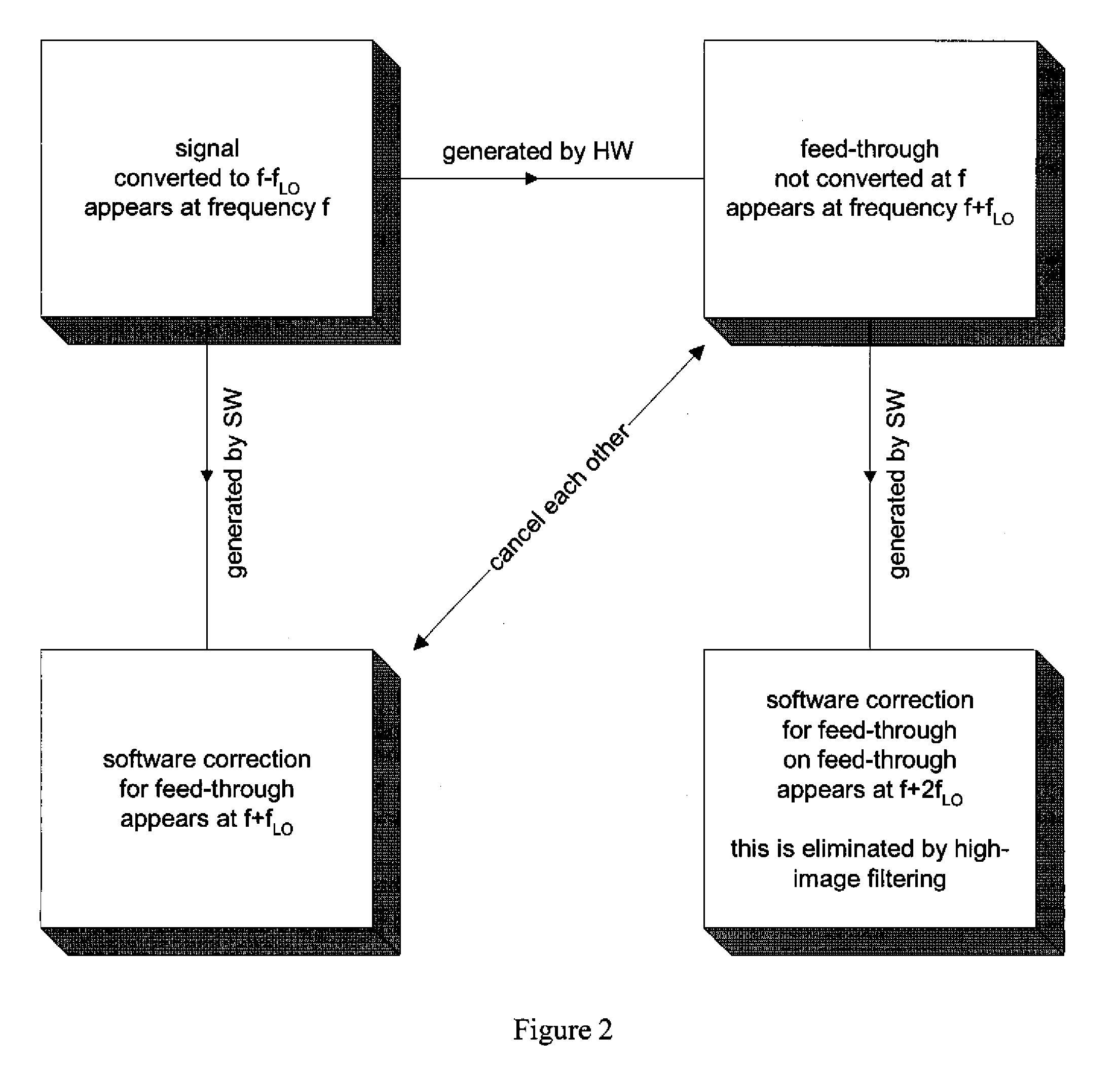
[0018]The invention will now be described making reference to the included Figures. Referring first to FIG. 1, a first case (down-side down-conversion) is shown. A signal of frequency f is first converted to fLO−f but the oscilloscope processing software may result in the signal appearing at frequency f. During processing the hardware system of the oscilloscope feeds through a portion of the signal that is not converted at frequency f, and thus appears at frequency fLO−f. In accordance with the invention, a software correction system is provided for correcting the feed-through that appears at frequency fLO−f. As is shown in FIG. 1, this software correction is designed to offset the feed-through error generated by the hardware portion of the system. Therefore, in accordance with further operation of the software system of the oscilloscope, the software correction for the feed-through appears at frequency fLO−f. While this correction will also change the amplitude of the signal at fre...


PUM


Abstract

A method for correcting feed through signals for use with an oscilloscope employing Digital Bandwidth Interleaving is provided. The method comprises the steps of converting an original signal to a frequency other than an original frequency of the original signal, determining one or more feed through signals not converted with the original signal, providing an offsetting correction signal and combining the converted signal, the non-converted feed through signal, and the offsetting correction signal.

Description

BACKGROUND OF THE INVENTION[0001]A digital bandwidth interleaving (DBI) oscilloscope (see, for example, U.S. Pat. Nos. 7,219,037; 7,139,684; 7,222,055; 7,058,548; 7,373,281; and U.S. patent application Ser. Nos. 11 / 525,345; 12 / 102,946; 12 / 112,218 the contents of these patents and applications being incorporated herein by reference) offers a remarkable solution for extending the bandwidth of oscilloscopes by allowing the high-frequency content of the acquired signal to be frequency shifted to a lower frequency range so that it can be acquired using channels that have a limited bandwidth. Hardware that has the specialized function of converting such higher frequency signals to a range of frequencies that are receivable by an existing digitizer technology typically use radio-frequency mixers surrounded by radio-frequency amplifiers and filters. Such a design has been demonstrated in several LeCroy® Corporation products employing a Digital Bandwidth Interleave method, such as the LeCroy...

Claims


Application Information

Patent Timeline
Patent Type & Authority Applications(United States)
IPC IPC(8): G01R23/00
CPCG01R13/0272
Inventor LAMARCHE, FRANCOISJOSHI, LAXMIKANTLIBBY, JONATHAN
Owner TELEDYNE LECROY
Why Eureka
Try Eureka