Capacity expansion control method for storage system

a control method and storage system technology, applied in error detection/correction, memory address/allocation/relocation, instruments, etc., can solve the problem of a long period of time for which the operation is suspended, the operation must be performed without backup (without fault tolerance) for a long period of time, and the period of time required for replication can be significantly reduced. the effect of reducing the time required for replication

Inactive Publication Date: 2009-04-09
NEC CORP
View PDF6 Cites 30 Cited by
  • Summary
  • Abstract
  • Description
  • Claims
  • Application Information

AI Technical Summary

Benefits of technology

[0017]According to the exemplary aspect of the invention, capacities of source and target logical volumes and difference maps thereof can be expanded while maintaining the pair relation and difference map information of the source and target logical volumes. Since the pair relation and the differenc

Problems solved by technology

Therefore, the period of time for which the operation is suspended becomes long if a difference is great.
(3) In step a9, the data must be fully copied for resynchronization, and hence a considerably long period of time is required before backing up the data.
This means that the operation must be performed without backup (without fault tolerance) for a long period of time.
The related art procedure as described above has problems that the operation suspension time is prolonged and the operation must be performed without backup for a long period of time.
Moreover, the operation suspension period is short.
(3) Resynchronization af

Method used


Image

  • Capacity expansion control method for storage system
  • Capacity expansion control method for storage system
  • Capacity expansion control method for storage system

Examples


first exemplary embodiment

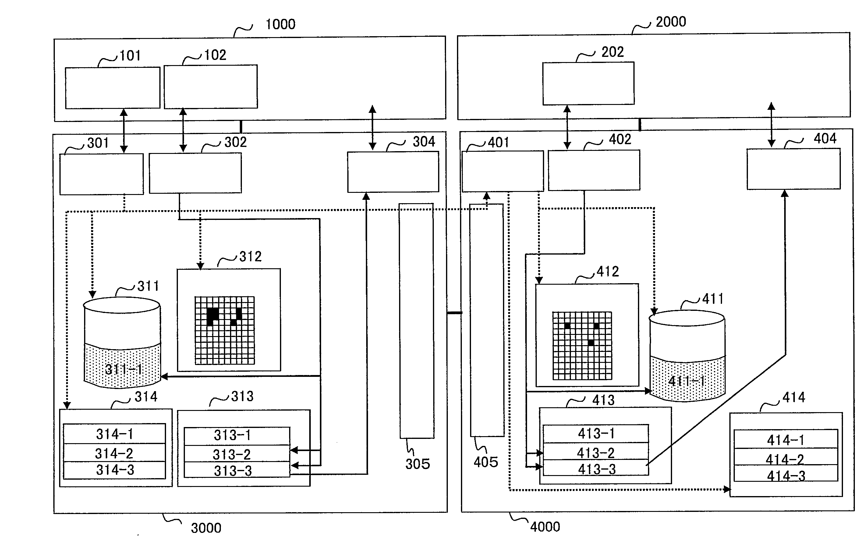
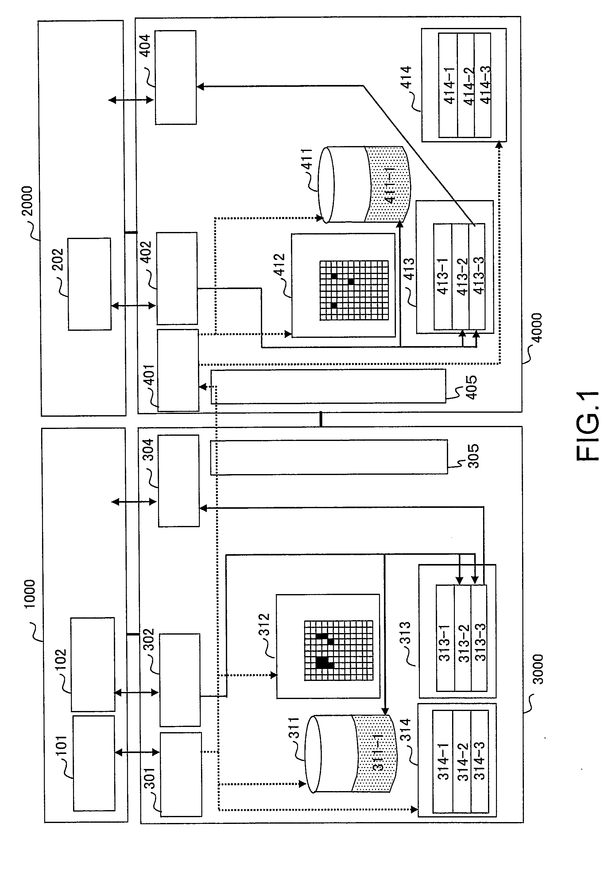
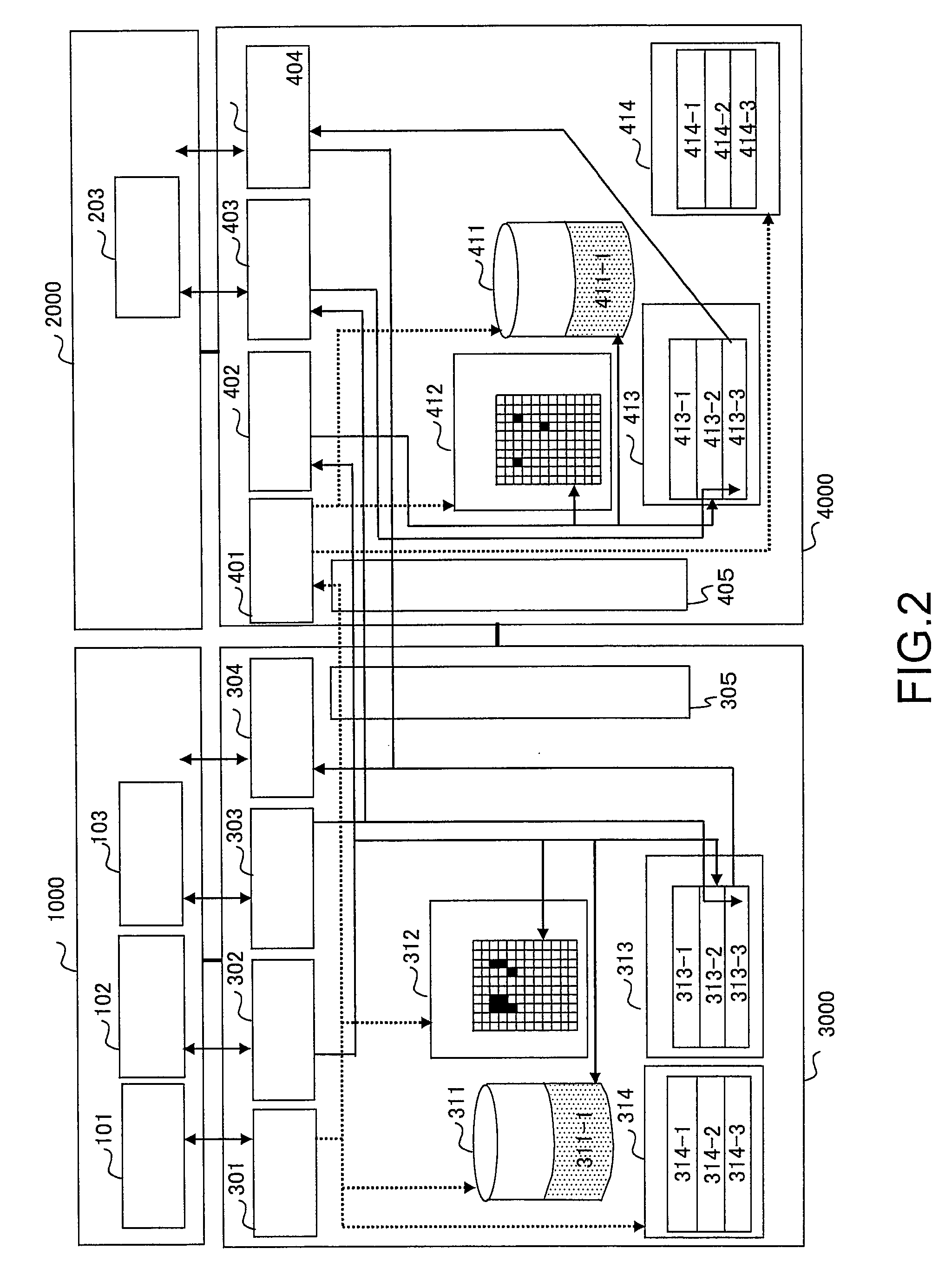
[0032]A first exemplary embodiment will be described in detail with reference to FIGS. 1 to 11. FIG. 2 shows a system block diagram according to the first embodiment. FIG. 4 is a flowchart showing a capacity expansion procedure in the REPLICATE mode and the SEPARATE mode according to the present invention. FIG. 6 shows an operational flowchart of a logical volume expansion operation unit according to the present invention. FIG. 7 shows an operational flowchart of the logical volume expansion unit according to the present invention, and detailed operational flowcharts of processing (1) to (4) therein are shown in FIGS. 8 to 11, respectively. A related art is shown in FIG. 1, FIG. 3, and FIG. 5 in order to facilitate the understanding of the embodiments of the present invention. FIG. 1 shows a system block diagram of the related art. FIGS. 3 and 5 show capacity expansion procedures in the REPLICATE mode and the SEPARATE mode, respectively, according to the related art.

[0033]The system...

second embodiment

[0124]A second embodiment of the present invention will be described in detail with reference to FIG. 12. FIG. 12 shows a system block diagram according to the second embodiment. In the second embodiment, the logical volume replication function is applied to logical volumes in one and the same disk array device.

[0125]As shown in FIG. 12, the system is composed of a server 1000 and a disk array device 3000. The server 1000 is a server to operate a business application, a backup application and the like. The disk array device 3000 is connected to the server 1000 through a fiber channel, and has a logical volume replication function. The server 1000 has a pair operating unit 101, a logical volume expansion operating unit 102, and a logical volume expansion recognition operating unit 103. These units provided in the server 1000 and their operations are the same as those described in relation to the first embodiment, and the description thereof will be omitted.

[0126]The disk array device...


PUM


Abstract

The invention provides capacity expansion control method for a storage system capable of expanding capacities of source and target logical volumes paired with each other and difference maps thereof while maintaining the pair relation between the source and target logical volumes and the difference map information thereof, and a storage system having such a capacity expansion control method.

Description

[0001]This application is based upon and claims the benefit of priority from Japanese Patent Application No. 2007-261622, filed on Oct. 5, 2007, the disclosure of which is incorporated herein in its entirety by reference.BACKGROUND OF THE INVENTION[0002]1. Field of the Invention[0003]The present invention relates to a storage system having a volume replication function, and particularly to a capacity expansion control method for expanding logical volumes in a storage system.[0004]2. Description of the Related Art[0005]The Computer system becomes large-scale, and a large amount of data is processed, and a larger amount of data is stored. An example of data storage devices (storage systems) is a disk array device in which a plurality of hard disks are integrated into one system. In general, a large amount of data is backed up by using a data replication technology, and stored in a disk array device as replicated and multiplexed data. A data storage area of the disk array device is div...

Claims


Application Information

Patent Timeline
IPC IPC(8): G06F12/16G06F13/00G06F12/02
CPCG06F11/2069G06F11/2071G06F11/2082
Inventor SANO, TAKANORI
Owner NEC CORP
Why Eureka
Try Eureka