
Seatbelt buckle apparatus

a seatbelt and buckle technology, applied in the direction of vehicle position/course/altitude control, process and machine control, instruments, etc., can solve the problems of poor usability, difficult to look for the position of the buckle apparatus, and the inability to keep the comfortable seating state, so as to speed up the wear of the seatbelt, improve the wear rate of the seatbelt, and improve the effect of comfor

Inactive Publication Date: 2009-04-16
TAKATA CORPORATION
View PDF29 Cites 24 Cited by
  • Summary
  • Abstract
  • Description
  • Claims
  • Application Information

AI Technical Summary

Benefits of technology

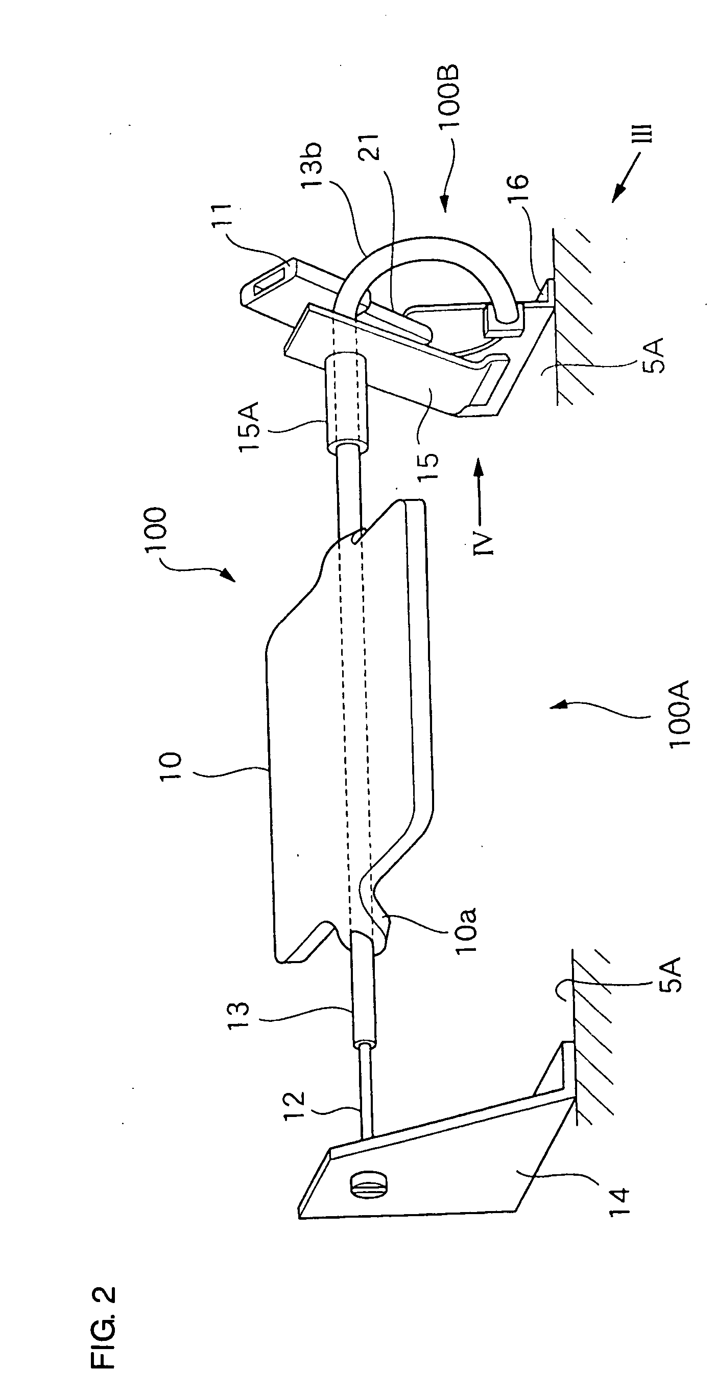
The present invention provides a seatbelt buckle apparatus that can stand up when an occupant is seated and insert the tongue of the seatbelt without needing an electric sensor or power source. The apparatus includes a buckle, a seating detection portion, and a load transmission-driving device that sends the displacement of the seating detection portion to the buckle to cause it to stand up and insert the tongue of the seatbelt. This mechanism is simple and efficient, improving the wearing rate of the seatbelt and making it easier for occupants to fasten their seatbelt.

Problems solved by technology

Specifically, in the rear seat of the bench seat type, since the occupant gets on a vehicle from a door at one side thereof, and sometimes moves widthwise while being seated, in the structure of the seatbelt apparatus where the buckle apparatus is projected from the seating surface, usability is not good.
Further, different from a driver seat, since a rear seat occupant is seated on various positions, it is difficult to look for a position of the buckle apparatus that is positioned between the seating portion and the lower end of the back portion, and the occupant should sometimes look for the buckle apparatus.
However, in a rear seat of a bench seat type, there has been a problem such that the occupant has seated on the buckle apparatus when the seatbelt is not yet worn, or that the buckle apparatus, which is not used, comes into contact with the body, and therefore a comfortable seating state cannot be kept.
Moreover, since a motor is used for moving the buckle, there is also a demand to make the same operation at an inexpensive equipment cost.

Method used


Image

  • Seatbelt buckle apparatus
  • Seatbelt buckle apparatus
  • Seatbelt buckle apparatus

Examples


first embodiment

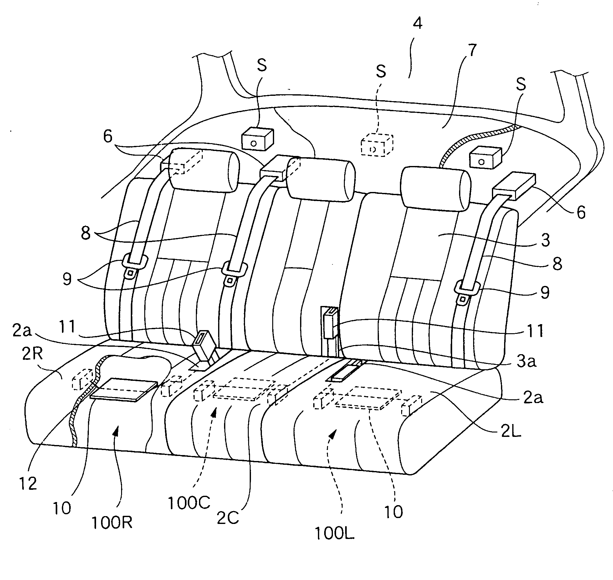
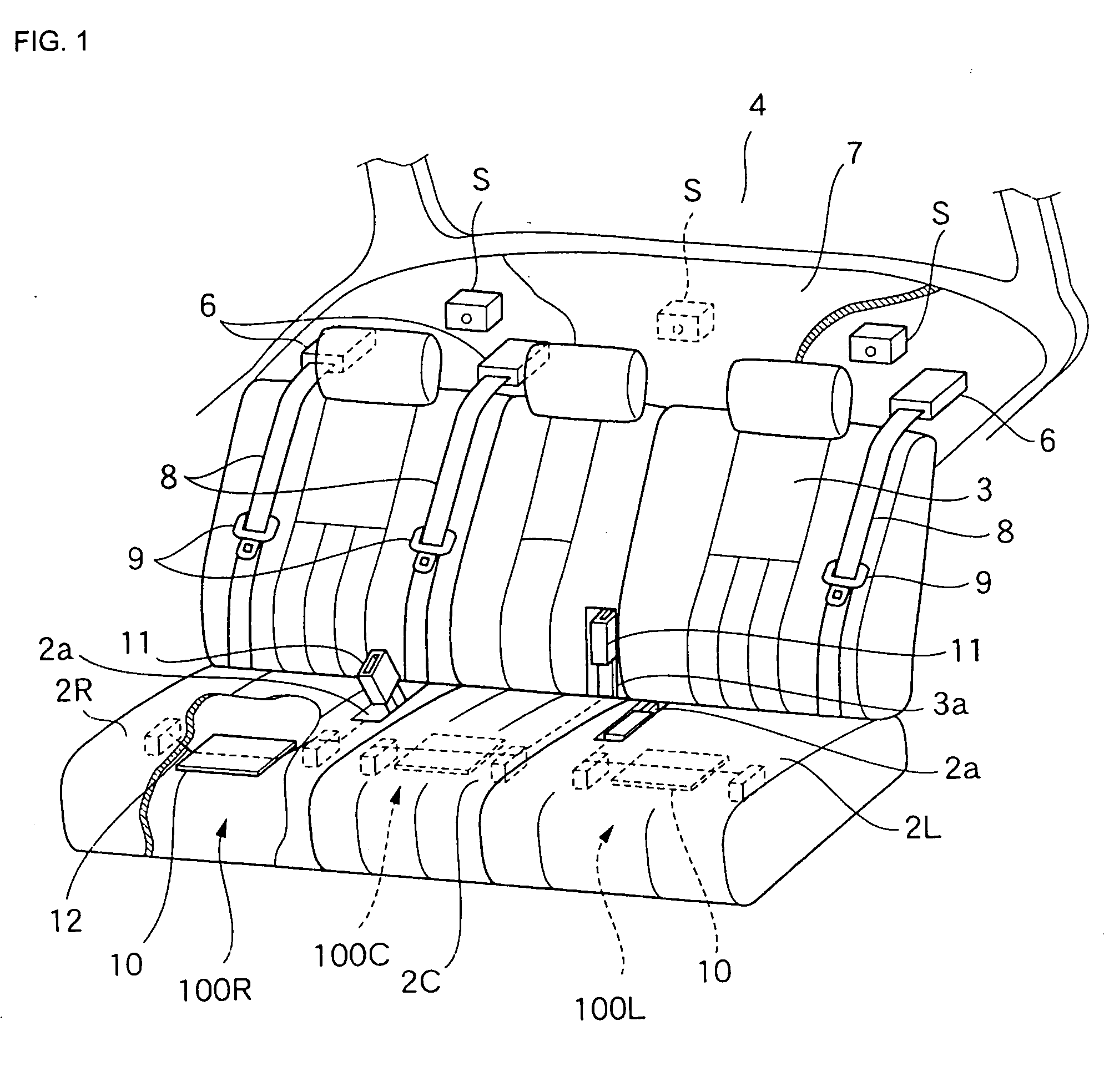
[0032]Seatbelt buckle apparatuses 100 of the present invention are housed inside seating portions 2L and 2R for occupants seated on the left and right door sides and a back portion 3C at a center of a seat in the seating portion 2 of a rear seat 1 as a triple seat of a vehicle, as illustrated in FIG. 1. In the first embodiment, a construction of a buckle apparatus, in which a buckle 11 housed in a cut-open portion 2a of the seating portion 2 stands up when the occupant on the left or right position is seated, and the buckle 11 is used in that state, will be explained. In the second embodiment, a construction of a buckle apparatus, in which the buckle 11 housed in a cut-open portion 3a provided in a part of a seat back 3 is projected in such a way that the buckle 11 is caused to fall forward, when the occupant is seated on the center of the rear seat 1, will be explained.

Construction of the Seatbelt Buckle Apparatus in the First Embodiment

[0033]FIG. 1 is a schematic perspective view ...


PUM


Abstract

A seatbelt buckle apparatus for attaching a tongue of a seatbelt includes a buckle projection mechanism having a buckle therein, to which the tongue of the seatbelt is to be inserted, a seating detection portion, and a load transmission-driving device. The buckle projection mechanism locates the buckle inside a seat when an occupant is not seated, and to stand up from the seat when the occupant is seated. The seating detection portion is housed in the seat at a seating position of the occupant and detects a load of the occupant. The seating detection portion has a supporting member. The load transmission-driving device transmits a displacement amount of the supporting member, generated in the seating detection portion when the occupant is seated, to the buckle projection mechanism, and drives the buckle projection mechanism so that the tongue can be inserted into the buckle when the occupant is seated.

Description

BACKGROUND OF THE INVENTION AND RELATED ART STATEMENT[0001]The present invention relates to a seatbelt buckle apparatus, and more specifically, it relates to a seatbelt buckle apparatus, in which in a rear seat of a vehicle or the like, a buckle is usually housed in an inside of a seat or a seat back, and an occupant can easily insert a tongue of a seatbelt into the buckle by causing the buckle to stand up from a seating surface, or by projecting the buckle from a seat back when the occupant is seated and wears the seatbelt.[0002]From Jun. 1, 2008 in Japan, an occupant seated in a rear seat of an automobile is legally obliged to wear a seatbelt. In general, since many of the rear seats are formed of a bench seat-type seat, different from a seatbelt apparatus of a driver's seat and a passenger's seat, a seatbelt apparatus having a self-sustaining structure, in which a buckle apparatus projects form a seating surface, has not been virtually adopted. Specifically, in the rear seat of t...

Claims


Application Information

Patent Timeline
Patent Type & Authority Applications(United States)
IPC IPC(8): B60R22/48
CPCB60R22/03Y10T24/45215B60R2022/266
Inventor SUGIMOTO, SHINICHITANAKA, KOJINOZU, HIROSHI
Owner TAKATA CORPORATION
Learn More