Ultralight Unit Load Device

Inactive Publication Date: 2009-04-16
DACUS WALTER
View PDF33 Cites 49 Cited by
  • Summary
  • Abstract
  • Description
  • Claims
  • Application Information

AI Technical Summary

Benefits of technology

[0010]It is an object of the invention to confer a lightweight, non-deformable unit load design that meets aviation industry standards without sacrificing payload capacity.
[0011]It is another object of the invention to provide a unit load design with a flat top profile for reducing the complexities of payload movement and the costs associated with cargo transportation without sacrificing payload capacity and structural integrity.
[0012]It is a further object of the invention to provide a durable structure that is resistant to impact damage and deformation with a multi-chambered open-structured edge profile that allows for elastic deformation in response to varying load conditions with minimal shear strain at the base plate intersection and is easy to replace when necessary.
[0017]The use of honeycomb core materials for constructing lightweight panels or sandwich structures is well established in the aeronautical and spacecraft fields. For example, in commercial aircraft, nearly all of the movable control surfaces, wing and tail leading and trailing edge fixed surfaces, doors, and interior cabin structures employ panels formed of honeycomb cores. Such prior art cores have typically been constructed of an aluminum or aramid paper honeycomb. Although more expensive than simple structures, the honeycomb core panel possess equal strength at higher stiffness, lower weight, and is resistant to higher natural vibration frequencies.

Problems solved by technology

The light-metal base plate of an air cargo pallet cannot insure heavy-load carrying capability by itself without being prone to deformation.
The raised profile of these constructions prohibit the free sliding movement of payloads, increasing the amount of time it takes to load and unload cargo and, commensurately, the costs of transport.
As in the instance of the slots mentioned above, the raised profile of this shoulder construction prohibits the free sliding movement of payloads, increasing the amount of time it takes to load and unload cargo and the commensurate costs.

Method used


Image

  • Ultralight Unit Load Device
  • Ultralight Unit Load Device
  • Ultralight Unit Load Device

Examples


Embodiment Construction

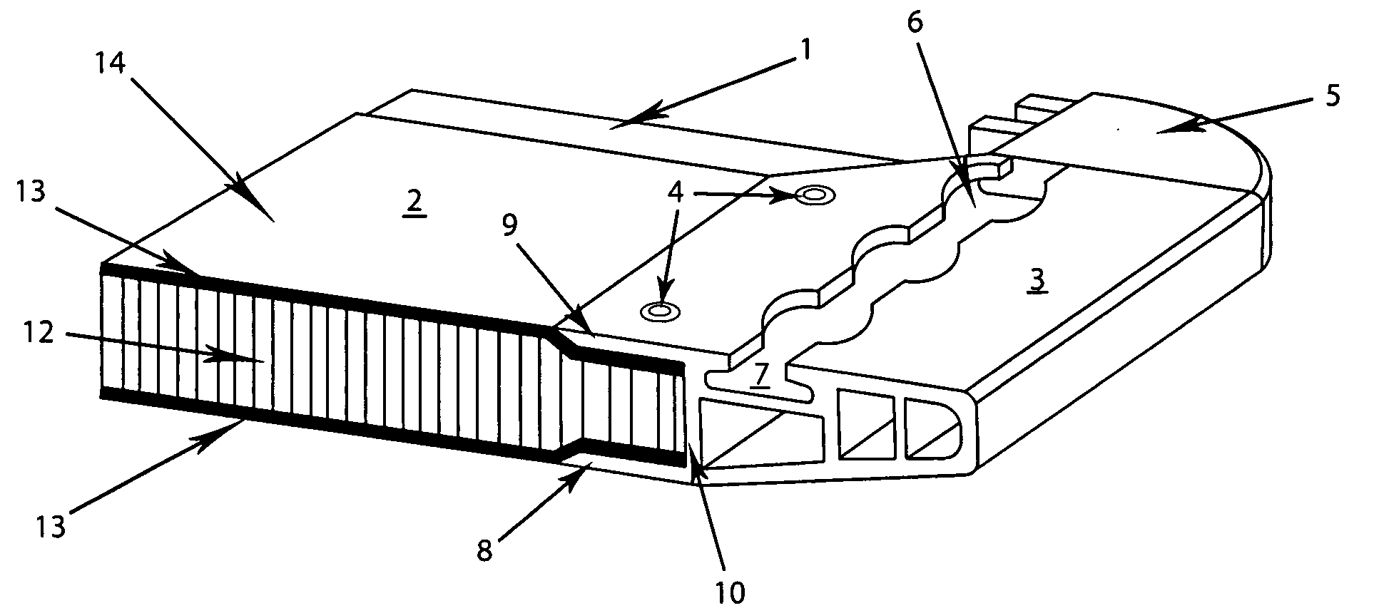
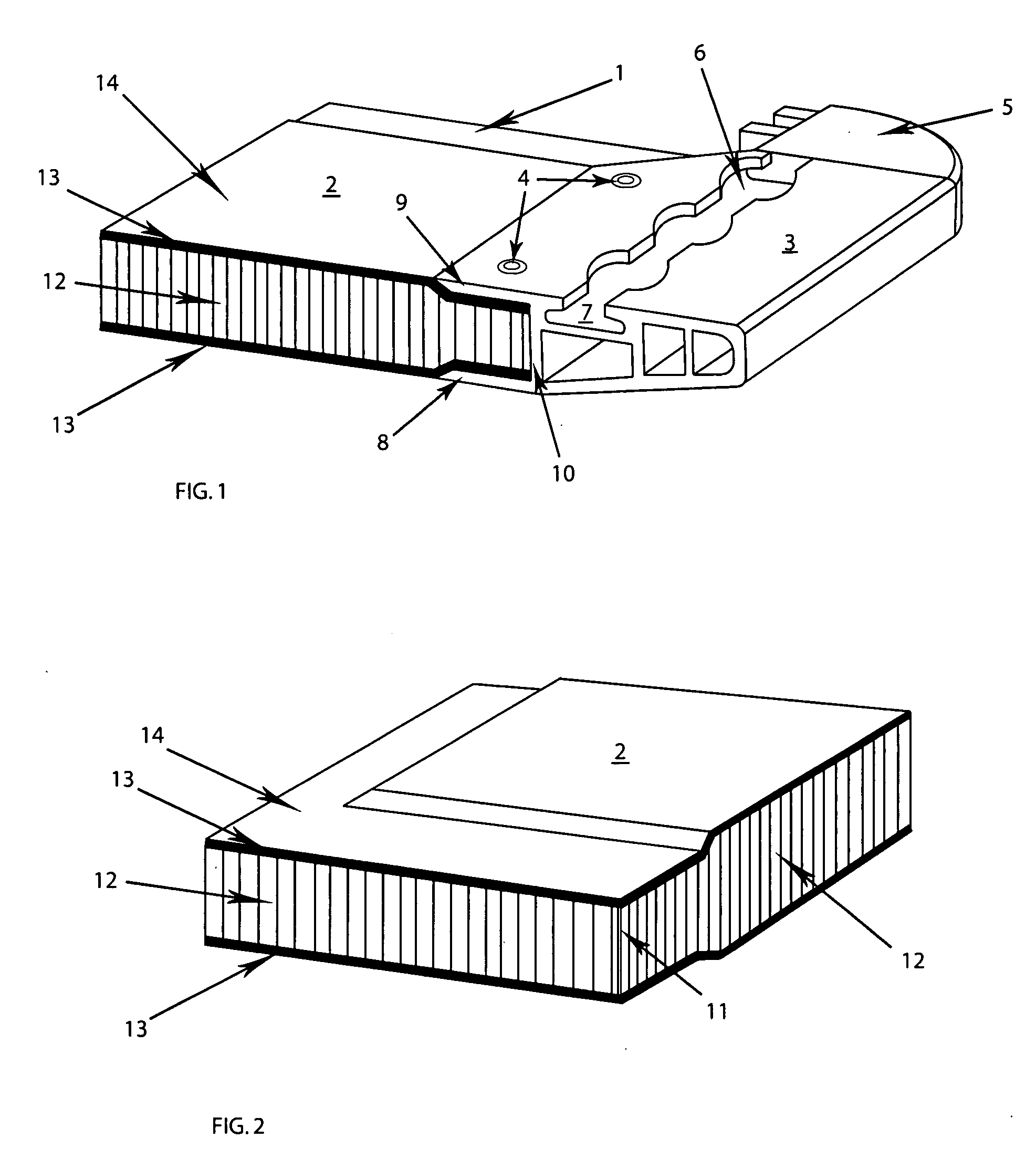
[0032]Referring now to the drawings, in which like reference numerals are used to refer to the same or similar elements, FIG. 1 shows a fragmentary, sectional, isometric view of the completed unit loading device assembly with reference number I designating a unit loading device constructed in accordance with the teachings of this invention. As seen from FIG. 1, the unit loading device 1 generally comprises of a unit base 2 and an at least one, but preferably a plurality of edge components 3 along each longitudinal and traverse edges of the unit base 2 and substantially equivalent to the length of the side of the unit base 2, although not necessarily so. In one embodiment of this invention, the edge component 3 is attached to the unit base 2 by attachment means such as a flush head rivet (not shown) at a plurality of apertures 4 in the edge component 3. Interconnecting the adjacent edge components 3 are corner sections 5 which will be discussed in further detail below. The edge compo...


PUM

PropertyMeasurementUnit
Temperatureaaaaaaaaaa
Lengthaaaaaaaaaa
Thicknessaaaaaaaaaa

Abstract

An ultralight unit load device comprising a ruggedized quadrangular composite structure with a cellular load-bearing core sealed in successive ordered-polymer stiffening plies and trimmed at the outer edges with a hollow, multi-chambered profile of lightweight material fixed with flush attachment means so as to present a flat surface for easy loading and unloading of payloads.

Description

FIELD AND BACKGROUND OF THE INVENTION[0001]The present invention relates generally to the field of ultralight unit load devices such as air cargo pallets and in particular to a ruggedized quadrangular composite structure with a cellular load-bearing core sealed in successive ordered-polymer stiffening plies and trimmed at the outer edges with a hollow, multi-chambered profile of lightweight material fixed with flush head rivets so as to present a flat surface for easy loading and unloading of payloads.[0002]The loading of air freight within the cargo compartment of an aircraft typically involves the use of pallets, available in a variety of different sizes, which are disposed in the aircraft and are otherwise designed to support and retain cargo thereon. A primary benefit to the use of such pallets is the ability to load a large volume of smaller items at one time, after they have been pre-loaded on the pallet at a remote location. Moreover, the pallet functions to maintain the item...

Claims


Application Information

Patent Timeline
IPC IPC(8): B65D19/06B29C70/00B65D19/38B32B5/00
CPCB29C70/088Y10T428/24149B29C70/865B29D99/0089B29K2705/00B32B3/12B65D19/0002B65D19/38B65D2519/00034B65D2519/00069B65D2519/00273B65D2519/00293B65D2519/00303B65D2519/00323B65D2519/00343B65D2519/00358B65D2519/00562B65D2519/00572B32B5/24B32B5/26B32B15/20B32B29/002B32B2250/40B32B2260/021B32B2260/046B32B2262/02B32B2262/101B32B2262/106B32B2307/558Y10T156/10B29C70/44
Inventor DACUS, WALTER
Owner DACUS WALTER
Why Eureka
Try Eureka