Container cleaning device, container cleaning method, and tank

a cleaning device and container technology, applied in the direction of cleaning process and apparatus, cleaning using liquids, lighting and heating apparatus, etc., can solve the problems of difficulty in continuously performing a series of treatments, and affecting the cleaning effect of containers with this type of protruding portion, so as to achieve the effect of cleaning uniformly

Inactive Publication Date: 2009-04-16
TOYOTA JIDOSHA KK
View PDF3 Cites 35 Cited by
  • Summary
  • Abstract
  • Description
  • Claims
  • Application Information

AI Technical Summary

Benefits of technology

[0109]In consequence, in consideration of the position of the jetting member in the container, a direction in which the fluid is jetted by the jetting member can be changed. Therefore, the inside of the container can evenly be cleaned without generating any dead angle in the container.

Problems solved by technology

Therefore, it has been difficult to continuously perform a series of treatments.
However, in the conventional cleaning device, the container having this type of protruding portion is not considered.
Therefore, for example, in the cleaning device disclosed in Patent Document 1, cleaning waste water resides so as to surround the protruding portion, and jetting from the nozzle for cleaning to this portion might be hampered.
Therefore, an operation of removing the cleaning waste water from the gas tank is required, and a series of treatments are not easily continuously performed.
Therefore, even if a cleaning liquid or a drying gas is jetted from the nozzle, these fluids do not reach the inner surface of the trunk portion, cleaning and drying are insufficiently performed, and the operation thus easily becomes complicated.
In consequence, a cleaning unevenness, a draining unevenness and the like are caused, a drying time is lengthened, and efficiency of a series of treatments thus deteriorates.

Method used


Image

  • Container cleaning device, container cleaning method, and tank
  • Container cleaning device, container cleaning method, and tank
  • Container cleaning device, container cleaning method, and tank

Examples


first embodiment

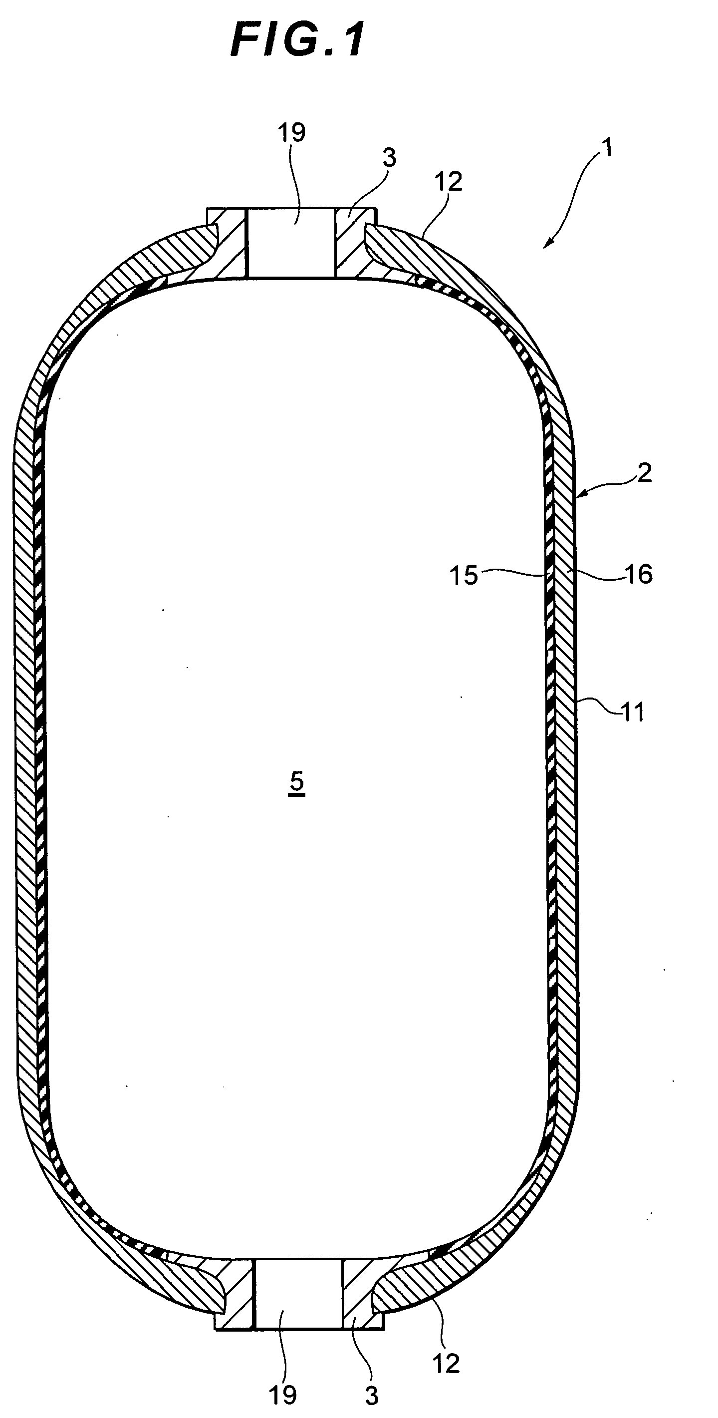
[0154]As shown in FIG. 1, a container 1 includes a container main body 2 having a hermetically closed cylindrical shape as a whole, and mouthpieces 3 attached to opposite end portions of the container main body 2 in a longitudinal direction. The inside of the container main body 2 (i.e., an inner part of the container) constitutes a storage space 5 to store various types of fluids such as a gas and a liquid. The container 1 may be filled with a normal-pressure fluid, and may be filled with a fluid having a pressure raised as compared with normal pressure. That is, the container 1 can function as a high-pressure tank.

[0155]For example, in a fuel cell system, a pressure of a fuel gas prepared in a high-pressure state is reduced to use the gas in power generation of a fuel cell. The gas container 1 may be applied to storage of a high-pressure combustible fuel gas, and a hydrogen gas, a compressed natural gas (a CNG gas) or the like as the fuel gas may be stored. A pressure of the hydro...

second embodiment

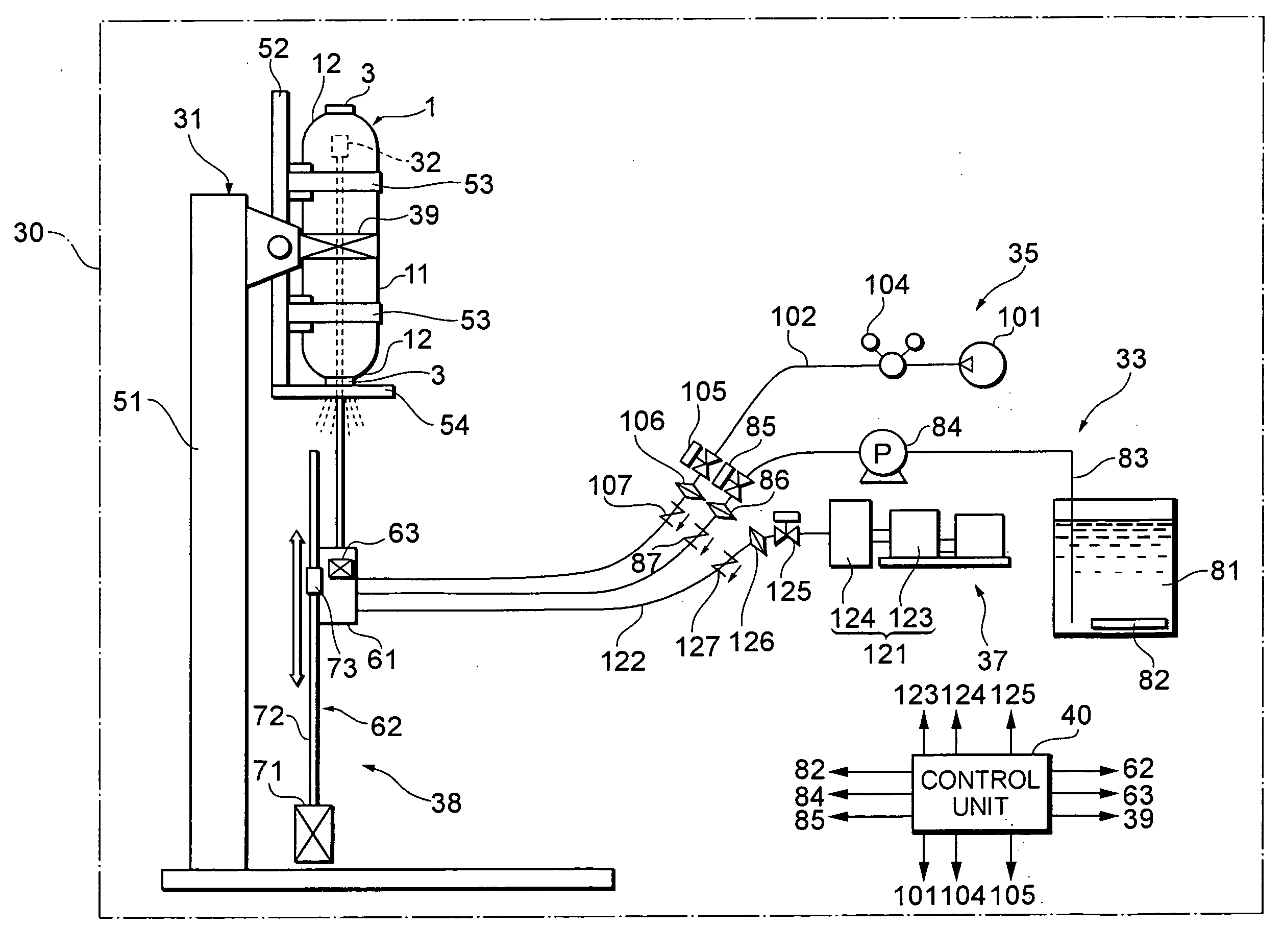
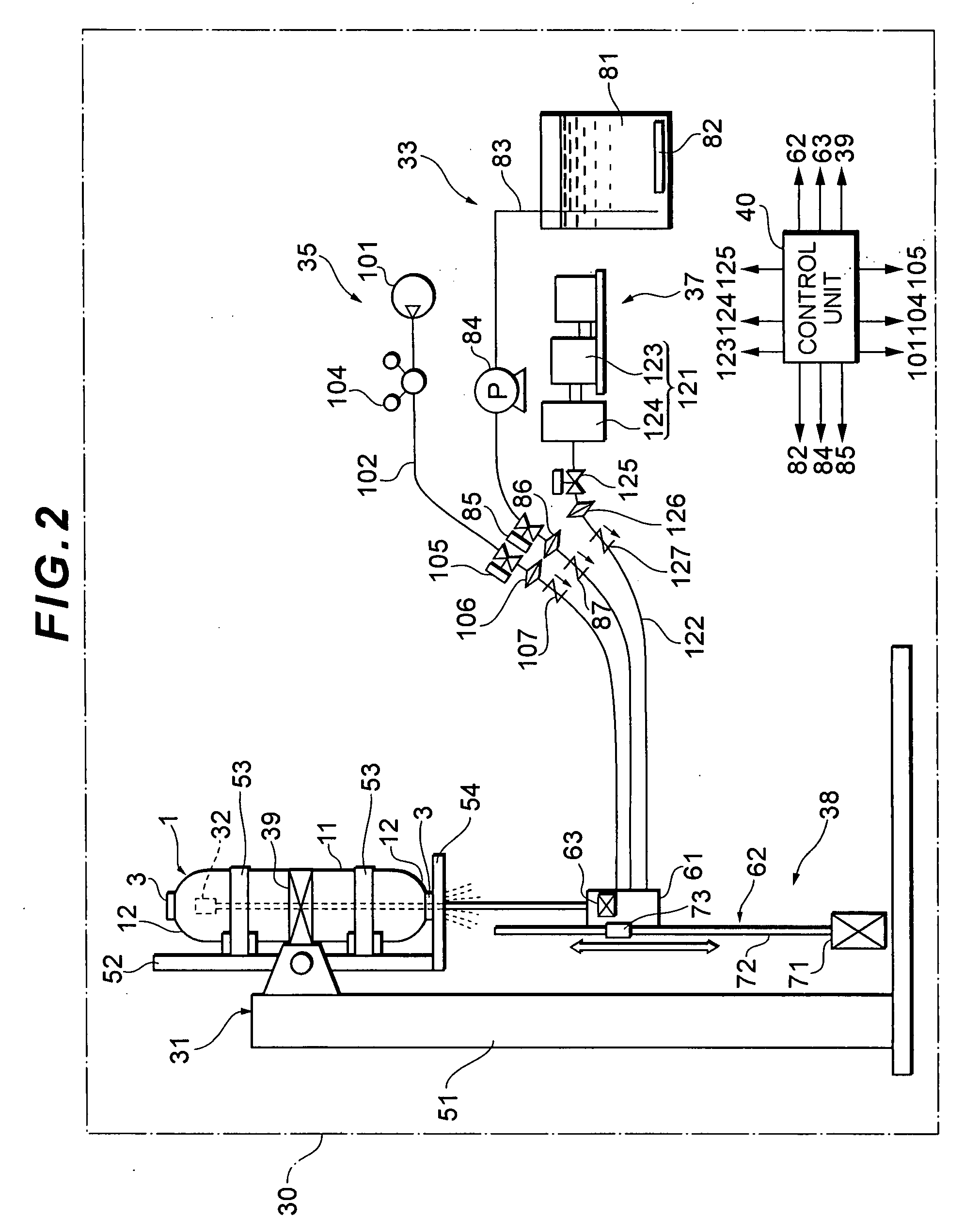
[0208]Next, a different respect of a cleaning device 30 according to a second embodiment will mainly be described with reference to FIG. 4. A large difference from the first embodiment lies in that various fluids such as a cleaning liquid, compressed air and hot air are jetted by a single nozzle 150.

[0209]Specifically, the single nozzle 150 as a jetting member has a single common jetting section 151 having jetting ports and a single common pipe 152 which communicates with the jetting section 151. A flexible hose 160 has a single common hose section 161, and three independent and individual hose sections 162, 163 and 164 corresponding to three fluids.

[0210]Ends of the three individual hose sections 162, 163 and 164 on one side are connected to the cleaning tank 81, the compressor 101 and the hot air generation unit 121, respectively. The other ends of the three individual hose sections 162, 163 and 164 are connected to input ports of a switch valve 167 of a four-way valve system. One...

third embodiment

[0216]Next, a different respect of a cleaning device 30 according to a third embodiment will mainly be described with reference to FIGS. 5 to 8. The embodiment is different from the first embodiment in that a shape of a container 1 is provided with protruding portions 13 as returning portions and that the container 1 is tilted, supported and rotated by the cleaning device 30. It is to be noted that in FIG. 7, a constitution of the container 1 is shown in a simplified manner.

[0217]FIG. 5 is a sectional view of the container 1. The container 1 includes the protruding portions 13, 13 which are formed at end wall portions 12, 12 and which protrude into a container main body 2. Each protruding portion 13 is provided at a mouth part of a liner 15 to which mouthpieces 3 are attached so as to turn back, and has a substantially cylindrical shape along an axis in an axial direction of the container 1. A donut-like space 18 is formed between an outer peripheral surface of each protruding porti...


PUM


Abstract

A cleaning device and a cleaning method for a container capable of continuously performing a cleaning treatment, and a tank. The cleaning device includes a jetting member which jets a fluid in the container; a movement unit which relatively moves the jetting member along an axial direction of the container with respect to the container so that the jetting member is inserted into the container from a mouth part of the container; and a switching unit which switches the jetting member from one function to another function. The switching unit switches a nozzle for a cleaning liquid, a nozzle for blowing and a nozzle for drying in order.

Description

TECHNICAL FIELD[0001]The present invention relates to a cleaning device and a cleaning method for a container for cleaning the inside of a container such as a tank, and a tank.BACKGROUND ART[0002]Heretofore, as a cleaning device for a container having a mouth part, a device has broadly been known in which an inner wall of the container is cleaned with a cleaning liquid and compressed air jetted from nozzles (e.g., see Patent Documents 1 to 7). In a cleaning device disclosed in Patent Document 1 in which the container is a gas tank, the mouth part of the gas tank is directed downwards, and a nozzle for cleaning is manually inserted into the gas tank from the mouth part thereof. After the cleaning liquid is jetted from the nozzle for cleaning, a nitrogen gas is injected into the gas tank to dry the inside of the gas tank. The nozzle that performs cleaning and drying treatments in this manner is formed into a cylindrical shape having a constant diameter from a tip end side to a base po...

Claims


Application Information

Patent Timeline
Patent Type & Authority Applications(United States)
IPC IPC(8): B08B9/093B08B9/42
CPCB08B9/34B08B9/0936B08B3/02B08B5/04B08B7/04F26B21/00
Inventor WAKAO, YOSHITAKAMURATE, MASASHI
Owner TOYOTA JIDOSHA KK
Why Eureka
Try Eureka