Sun-tracking power generating apparatus

Inactive Publication Date: 2009-04-16
LIN CHIEN FENG +2
View PDF6 Cites 17 Cited by
  • Summary
  • Abstract
  • Description
  • Claims
  • Application Information

AI Technical Summary

Benefits of technology

[0006]With the above arrangements, the solar-tracking power generating apparatus could more accurately track the solar position and focus more sun

Problems solved by technology

However, the photosensitive resistors have relatively large sensing error, and the conventional solar-trackin

Method used


Image

  • Sun-tracking power generating apparatus
  • Sun-tracking power generating apparatus
  • Sun-tracking power generating apparatus

Examples


Embodiment Construction

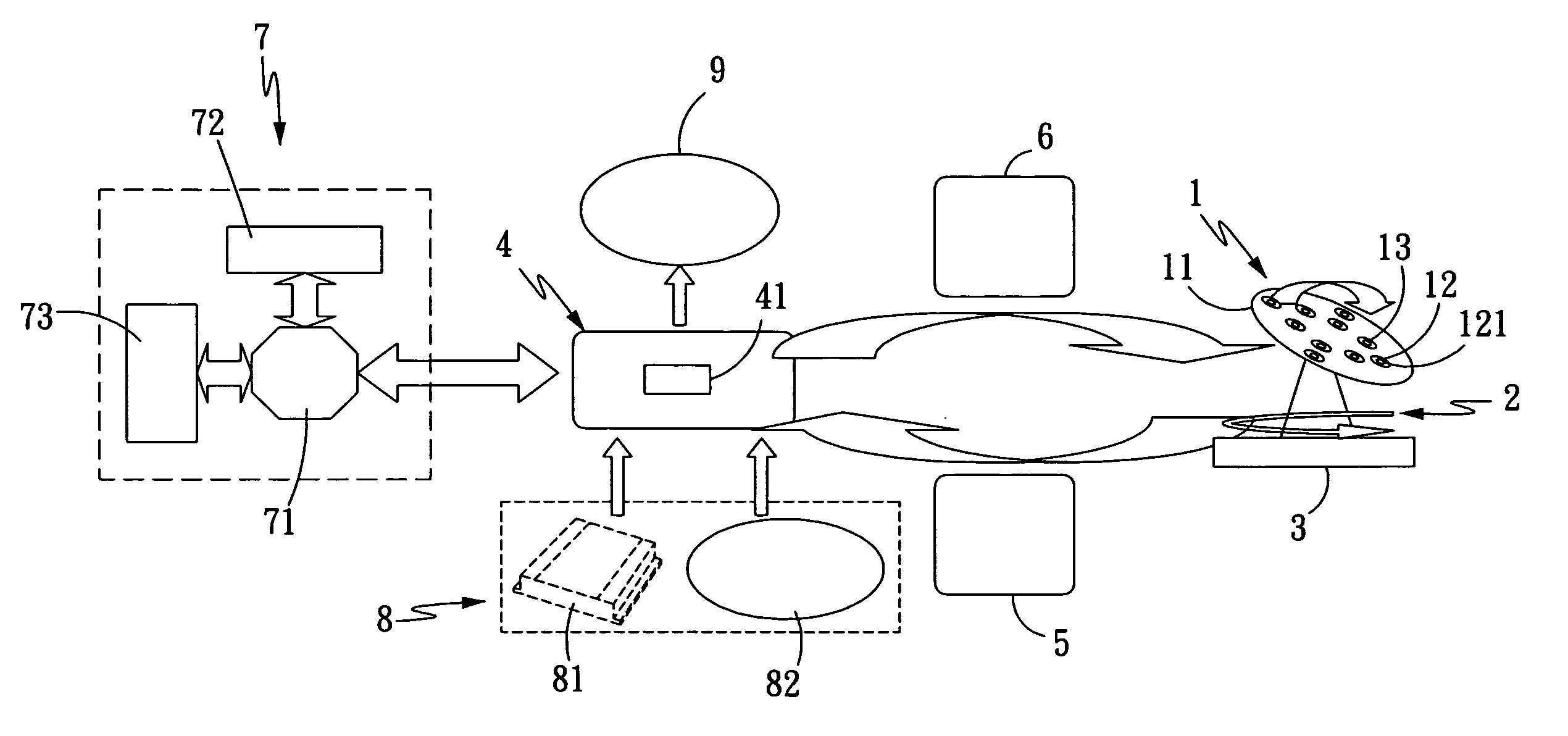
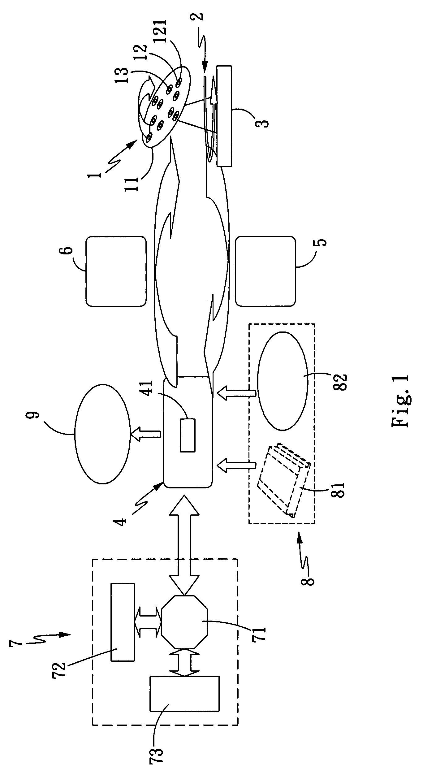
[0014]Please refer to FIG. 1 that is a conceptual view of a sun-tracking power generating apparatus according to a preferred embodiment of the present invention. As shown, the sun-tracking power generating apparatus of the present invention includes a sun-tracking unit 1, a transmission unit 2, a control unit 4, a solar trajectory simulation unit 7, and an input unit 8.

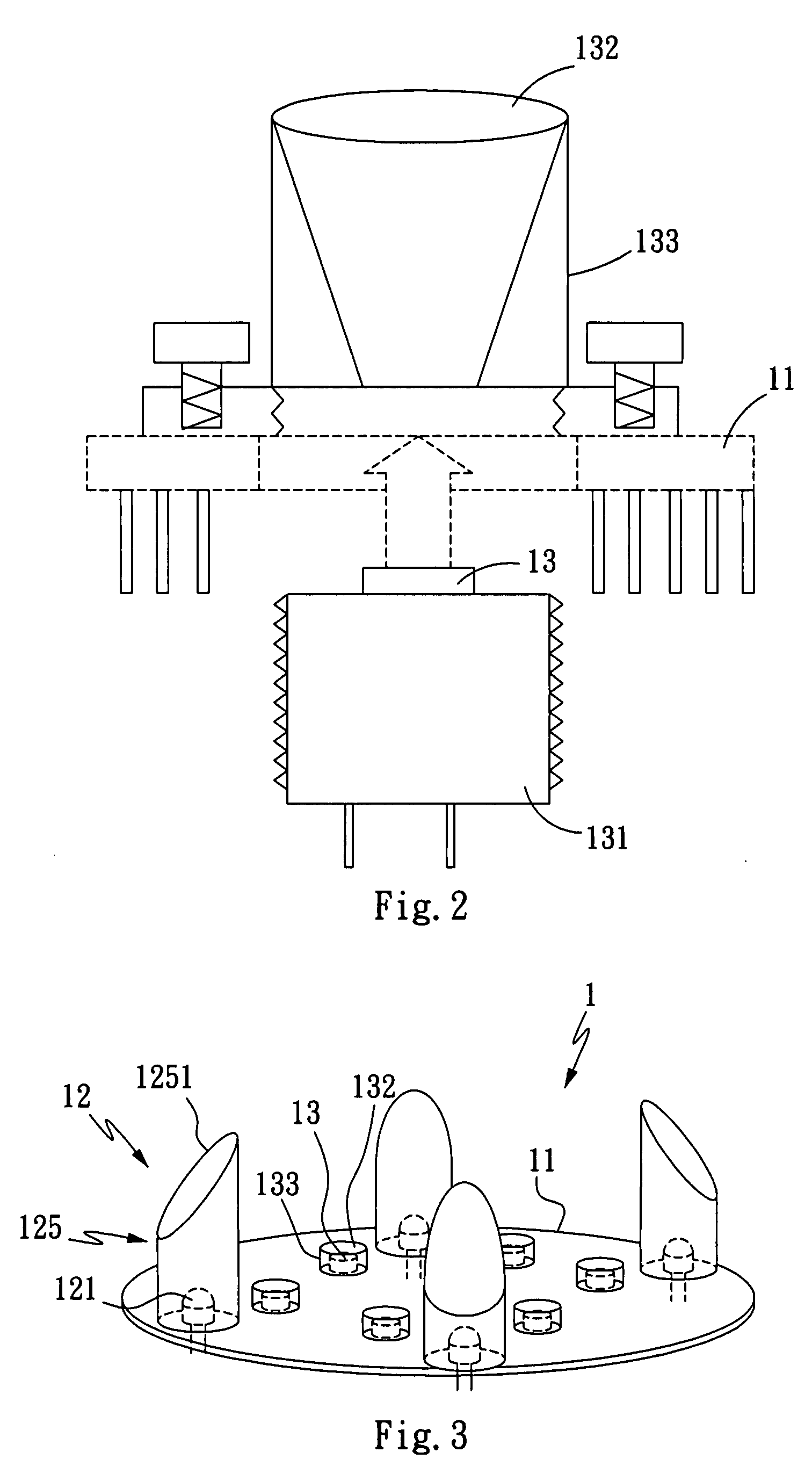
[0015]The solar-tracking unit 1 includes a disc 11 being provided on an upper side with two pairs of sensing units 12 and a plurality of solar batteries 13. The two sensing units 12 in each pair are diametrically opposite to each other, such that two straight lines containing the two pairs of sensing units 12 perpendicularly intersect with each other at a center of the disc 11 to equally divide the 360-degree central angle of the disc 11, and the two sensing units 12 in each pair are equally distant from the center of the disc 11. Each of the sensing units 12 includes a solar battery sensor (or a photosensitive diode ...


PUM


Abstract

A solar-tracking power generating apparatus includes a plurality of sensing units having a directional light-extraction member each, a plurality of solar batteries associated with a light-gathering device each, and a solar trajectory simulation unit. Therefore, the solar-tracking power generating apparatus enables more accurate tracking of solar position and focusing of more sunlight on the solar batteries, so that the solar batteries could absorb more sunlight and convert the same into an increased amount of electric power.

Description

FIELD OF THE INVENTION[0001]The present invention relates to a solar-tracking power generating apparatus, and more particularly to a solar-tracking power generating apparatus that includes a plurality of sensing units and solar batteries with improved light-extraction ability, and a solar trajectory simulation unit.BACKGROUND OF THE INVENTION[0002]Considering the threatening depletion of petrochemical fuels available on the earth, other types of energy sources, such as solar power generation, wind power generation, and water power generation, have been positively exploited by people to replace the petrochemical fuels. In the case of solar power generation, there is included a solar collector panel, which is oriented to the sun for one or more solar batteries to absorb sunlight and convert the same into electric energy. For the solar collector panel to always face toward the sun, a solar-tracking apparatus is additionally mounted to the solar collector panel. A conventional solar-tra...

Claims


Application Information

Patent Timeline
IPC IPC(8): H01L31/048
CPCF24J2/38G01S3/7861H02S20/00Y02E10/50G05D3/105F24S50/20H02S20/10H02S20/32H02S40/22Y02E10/52
Inventor LIN, CHIEN-FENGLIN, CHUAN-YICHEN, CHENG-MIN
Owner LIN CHIEN FENG
Why Eureka
Try Eureka