Flask unit and cope-and-drag molding machine and line

a molding machine and copeanddrag technology, applied in the direction of moulding machines, foundry patterns, moulding apparatus, etc., can solve the problems of defective castings that have fins or the lik

Active Publication Date: 2009-04-16
SINTOKOGIO LTD
View PDF4 Cites 8 Cited by
  • Summary
  • Abstract
  • Description
  • Claims
  • Application Information

AI Technical Summary

Problems solved by technology

This inherently causes a problem in that a de...

Method used


Image

  • Flask unit and cope-and-drag molding machine and line
  • Flask unit and cope-and-drag molding machine and line
  • Flask unit and cope-and-drag molding machine and line

Examples


Embodiment Construction

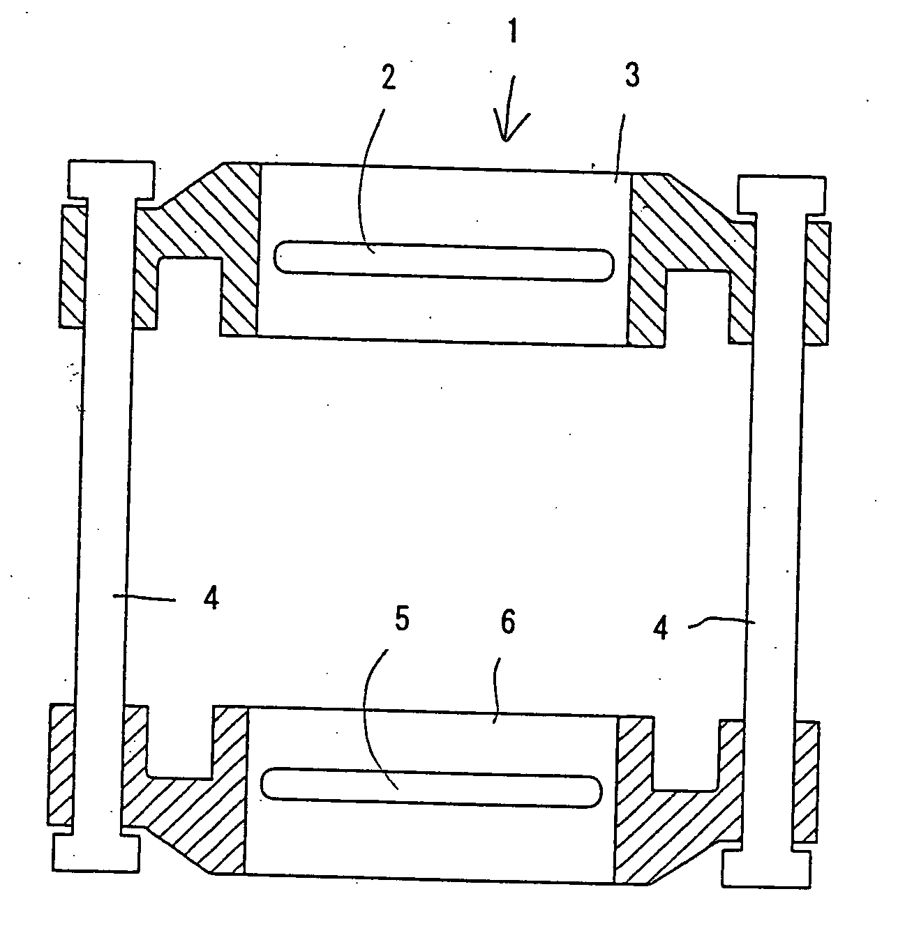
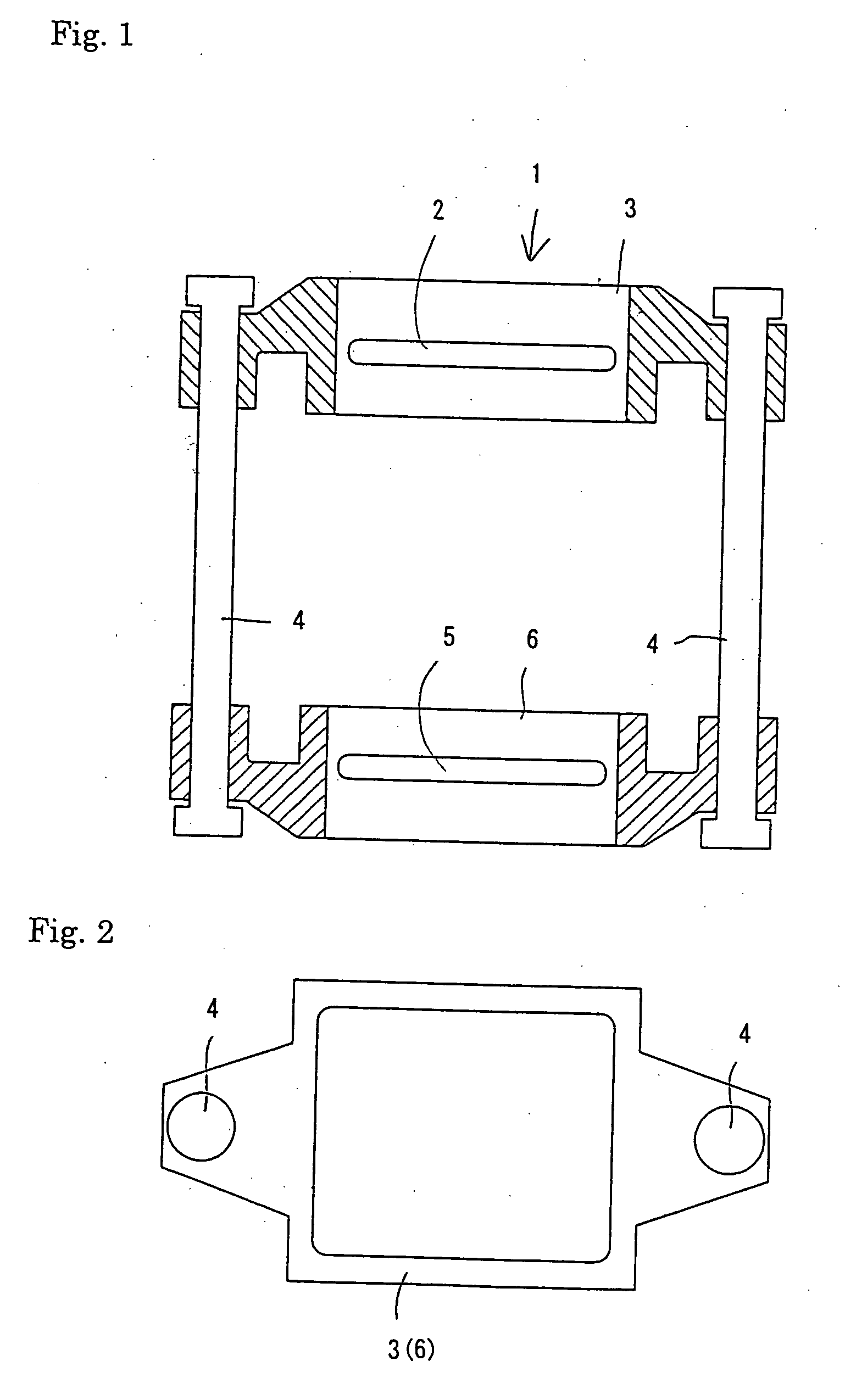
[0019]In FIGS. 1 and 2, the best mode of the flask unit 1 of the present invention comprises a cope flask 3, two connecting rods 4, 4 on which the cope flask is slidably mounted or fitted, and a drag flask 6 slidably mounted, or fitted, on the two connecting rods 4, 4 so that it is located under the cope flask 3. The cope flask 3 is formed with a molding sand blowing-in port 2 in one of its sides, and the drag flask is also formed with a molding sand blowing-in port 5 in one of its sides.

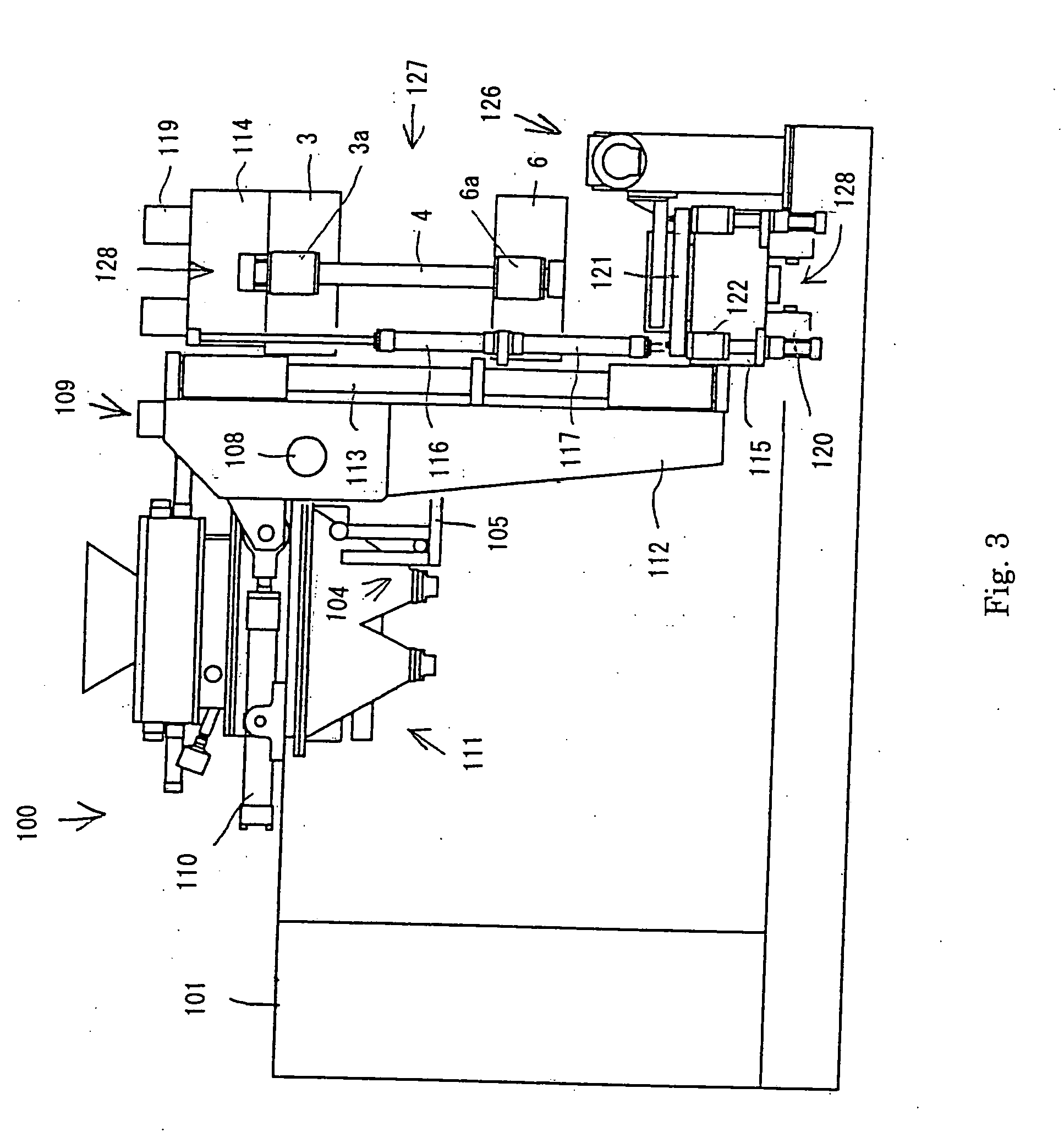
[0020]One embodiment of the cope-and-flask molding machine 100 of the present invention, which uses the flask unit 1 detachably mounted on it, is now explained based on FIGS. 3-5. The cope-and-flask molding machine 100 comprises a machine base 101 defining a space therein; a match plate 105 mounted to be placed in and out of a position between the cope flask 3 and the drag flask 6 of the flask unit 1 by a transfer mechanism 104; a molding sand squeeze mechanism 109 to which the flask unit 1 is detac...


PUM


Abstract

A flask unit for producing a cope and a drag that are stacked, comprising at least two uprightly disposed connecting rods (4), a cope flask slidably fitted on the connecting rods and formed with a molding sand blowing-in port in one of its sides, and a drag flask slidably fitted on the connecting rods so that it is located under the cope flask to mate it, the drag flask being formed with a molding sand blowing-in port in one of the sides thereof.

Description

FIELD OF THE INVENTION[0001]This invention relates to a flask unit and a cope-and-drag molding machine and line for molding a flaskless or flask-tight cope and drag using the flask unit.BACKGROUND ART[0002]JP A 7-16705 discloses one conventional molding machine. This machine is a horizontally split type molding machine that includes a molding sand blowing tank with downwardly-facing nozzles, and an L-shaped frame carrying a cope on the vertical surface of the vertical side of the L-shaped frame so that the cope is vertically moved and also carrying a drag on the horizontal surface of the horizontal side of the L-shaped frame so that the drag is reciprocatingly moved between a position opposing the cope and another position that is outside the opposing position, wherein the L-shaped frame is rotatable between a position outside the molding sand blowing tank and another position under the tank.[0003]In this conventional molding machine arranged as explained above, the cope and the dra...

Claims


Application Information

Patent Timeline
IPC IPC(8): B22C21/02B22C11/00B22C15/28
CPCB22C11/10B22C21/02B22C15/28B22C15/30B22C17/00
Inventor HIRATA, MINORU
Owner SINTOKOGIO LTD
Why Eureka
Try Eureka