
Wireless Devices Including Printed Integrated Circuitry and Methods for Manufacturing and Using the Same

a technology of printed integrated circuits and wireless devices, applied in the field of sensors and electronic article surveillance, can solve the problems of increasing the cost limitation associated with attaching, reducing the incentive to manufacture smaller integrated circuits, etc., and achieves the effects of reducing capital expenditure and operating costs, reducing manufacturing costs, and increasing material utilization

Inactive Publication Date: 2009-04-16
ENSURGE MICROPOWER ASA
View PDF19 Cites 49 Cited by
  • Summary
  • Abstract
  • Description
  • Claims
  • Application Information

AI Technical Summary

Benefits of technology

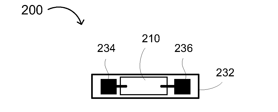
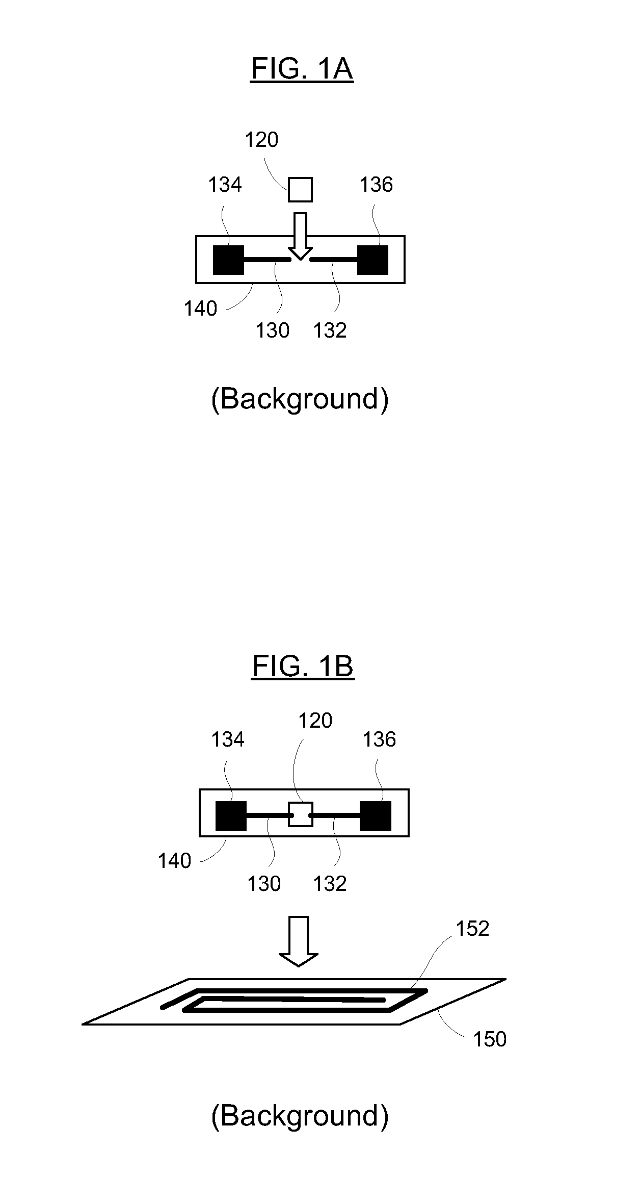
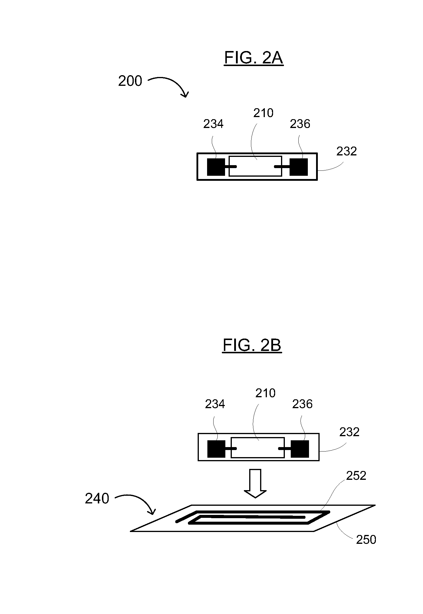
"The present invention relates to a method and device for manufacturing low-cost RFID tags using printed integrated circuitry with an attached antenna. The method involves forming printed integrated circuitry on a first substrate, adding pads to the circuitry, and attaching the pads to a separate antenna or inductor on a second substrate. The method reduces the cost of manufacturing by using printing techniques that increase materials utilization and combine deposition and patterning steps. The invention also provides a low-cost method for manufacturing larger integrated circuitry while reducing costs over conventional manufacturing processes. The invention advantageously reduces the number of expensive and low-throughput attachment steps, as well as the cost of fabricating the active electronics, resulting in a low-cost tag."

Problems solved by technology

The incentive to manufacture smaller integrated circuits is diminished and cost limitations associated with the cost of attach become prevalent.
This approach diverges from the conventional semiconductor wafer cost reduction approach of reducing die cost by decreasing die size (although this approach may become self-limiting for direct-attached silicon RFID tags, as the attach costs increase for smaller die).

Method used


Image

  • Wireless Devices Including Printed Integrated Circuitry and Methods for Manufacturing and Using the Same
  • Wireless Devices Including Printed Integrated Circuitry and Methods for Manufacturing and Using the Same
  • Wireless Devices Including Printed Integrated Circuitry and Methods for Manufacturing and Using the Same

Examples


Embodiment Construction

[0026]Reference will now be made in detail to the preferred embodiments of the invention, examples of which are illustrated in the accompanying drawings. While the invention will be described in conjunction with the preferred embodiments, it will be understood that they are not intended to limit the invention to these embodiments. On the contrary, the invention is intended to cover alternatives, modifications and equivalents that may be included within the spirit and scope of the invention as defined by the appended claims. Furthermore, in the following detailed description of the present invention, numerous specific details are set forth in order to provide a thorough understanding of the present invention. However, it will be readily apparent to one skilled in the art that the present invention may be practiced without these specific details. In other instances, well-known methods, procedures, components, and circuits have not been described in detail so as not to unnecessarily ob...


PUM

PropertyMeasurementUnit
areaaaaaaaaaaa
areaaaaaaaaaaa
temperatureaaaaaaaaaa

Abstract

Printed integrated circuitry and attached antenna and / or inductor for sensors, electronic article surveillance (EAS), radio frequency (RF) and / or RF identification (RFID) tags and devices, and methods for its manufacture. The tag generally includes printed integrated circuitry on one carrier and an antenna and / or inductor on another carrier, the integrated circuitry being electrically coupled to the antenna and / or inductor. The method of manufacture generally includes of printing an integrated circuit having a plurality of first pads on a carrier, forming an antenna and / or inductor having a plurality of second pads on a substrate, and attaching at least two of the first pads of the printed integrated circuit to corresponding second pads of the antenna and / or inductor. The present invention advantageously provides a low cost RFID tag capable of operating at MHz frequencies that can be manufactured in a shorter time period than conventional RFID tags that manufacture all active electrical devices on a conventional wafer.

Description

RELATED APPLICATIONS[0001]This application claims the benefit of U.S. Provisional Application No. 60 / 979,057, filed Oct. 10, 2007 (Attorney Docket No. IDR1611), and U.S. Provisional Application No. 60 / 980,581, filed Oct. 17, 2007 (Attorney Docket No. IDR0571), both of which are incorporated herein by reference in their entireties.FIELD OF THE INVENTION[0002]The present invention generally relates to the field of sensors and electronic article surveillance (EAS), radio frequency (RF) and / or RF identification (RFID) tags and devices. More specifically, embodiments of the present invention pertain to tags / devices utilizing printed integrated circuitry with an attached antenna, typically EAS, RF and / or RFID tags and devices, and methods for their manufacturing and / or production. As a result, the present invention may provide a low-cost process for producing an RFID (or EAS) tag comprising printed integrated circuitry and an antenna.BACKGROUND OF THE INVENTION[0003]Remotely powered elect...

Claims


Application Information

Patent Timeline
Patent Type & Authority Applications(United States)
IPC IPC(8): G06K19/06H05K3/00H04Q5/22
CPCG06K19/07749Y10T29/49124G06K19/0775G06K19/07752
Inventor SMITH, PATRICKCHOI, CRISWELLPAVATE, VIKRAMCLEEVES, JAMES MONTAGUESUBRAMANIAN, VIVEKYOUNG, RICHARDBIVIANO, VINCE
Owner ENSURGE MICROPOWER ASA
Learn More