
Video communication device and camera tracking method thereof

a technology of video communication and camera tracking, which is applied in the field of video communication device and camera tracking method, can solve the problems of poor video telephony quality and improper recording of images, and achieve the effect of improving video telephony quality and wide angular field

Active Publication Date: 2009-04-16
SAMSUNG ELECTRONICS CO LTD
View PDF10 Cites 43 Cited by
  • Summary
  • Abstract
  • Description
  • Claims
  • Application Information

AI Technical Summary

Benefits of technology

[0006]To address the above-discussed deficiencies of the prior art, it is a primary object to provide a video communication device and a camera tracking method thereof, which can locate a moving object through a detection unit, such as a voice sensor, a coder-decoder (codec), a color sensor and an infrared (IR) sensor, and automatically track the object by suitably adjusting the rotation angle of a camera, so that a wide angular field is ensured, a user can feel as if he / she is talking with a counterpart in person, and video telephony quality is improved.
[0010]Here, the voice sensor provided as the detection unit can detect the object located in a place where a relatively louder sound is produced than other places. Alternatively, it is possible to set the voice sensor to detect the object located in a place where a relatively softer sound is produced than other places.
[0015]According to the invention as set forth above, a moving object can be located through a detection unit, such as a voice sensor, a coder-decoder (codec), a color sensor and an infrared (IR) sensor, and be automatically tracked by suitable adjustment of the rotation angle of a camera. Accordingly, a wide angular field is ensured, the user can feel as if he / she is talking with a counterpart in person, and video telephony quality is improved.

Problems solved by technology

Accordingly, the images are not properly recorded or displayed, and video telephony quality is poor.

Method used


Image

  • Video communication device and camera tracking method thereof
  • Video communication device and camera tracking method thereof
  • Video communication device and camera tracking method thereof

Examples


Embodiment Construction

[0026]FIGS. 1 through 8, discussed below, and the various embodiments used to describe the principles of the present disclosure in this patent document are by way of illustration only and should not be construed in any way to limit the scope of the disclosure. Those skilled in the art will understand that the principles of the present disclosure may be implemented in any suitably arranged video communication device.

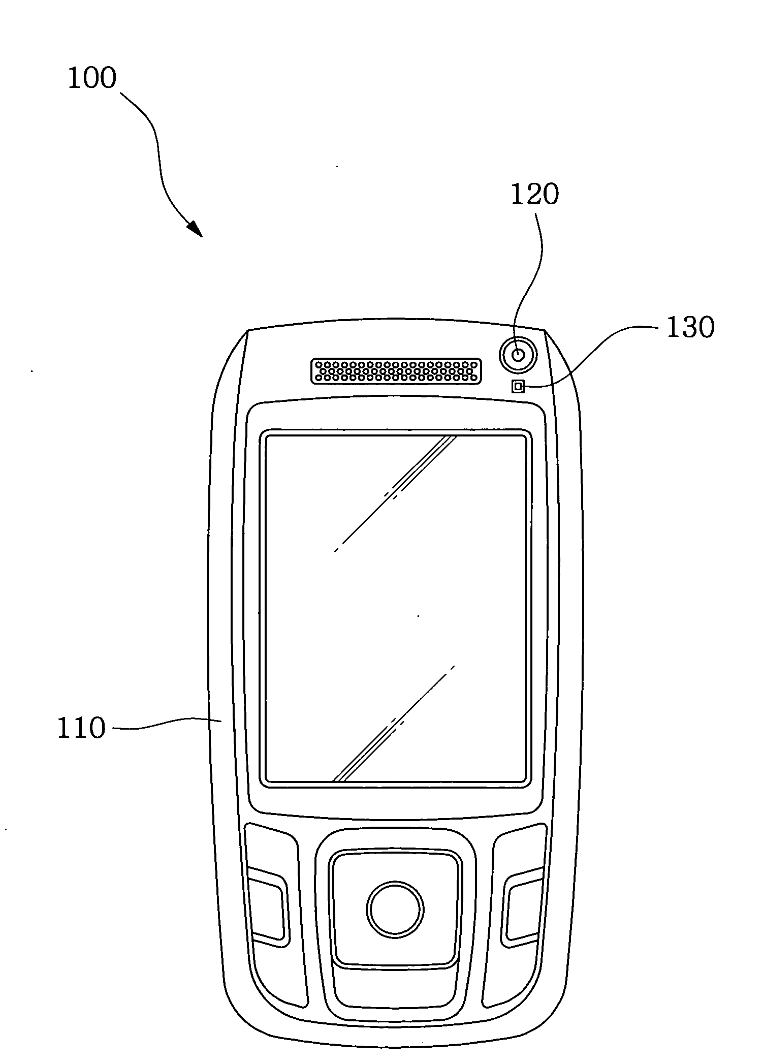
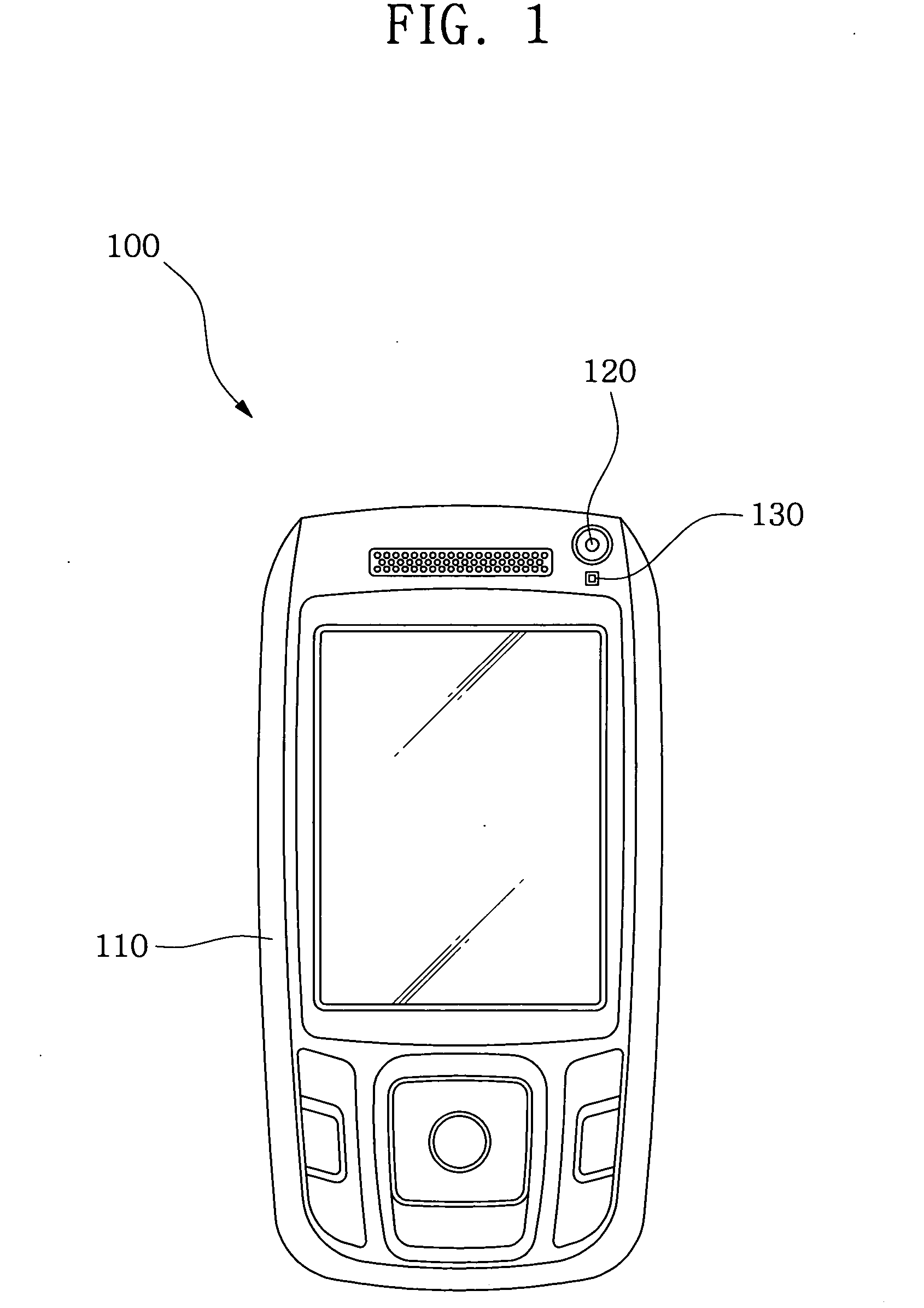
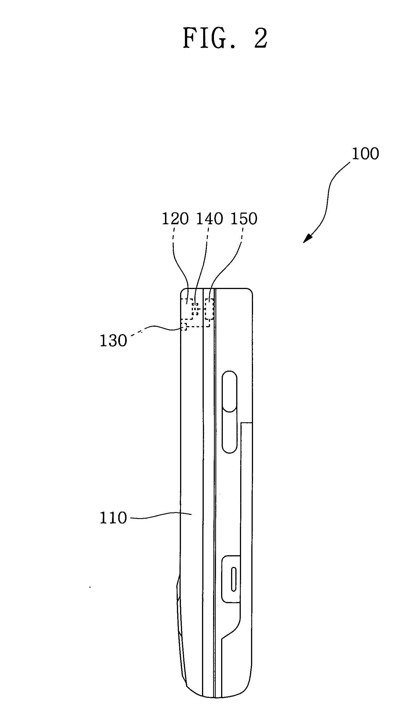
[0027]FIG. 1 is a front elevation view of a video communication device 100 of the invention, and FIG. 2 is a side elevation view of the video communication device 100 of the invention.

[0028]Referring to FIGS. 1 and 2, the video communication device 100 includes a video communication device body 110 and a camera 120, which is disposed in the video communication device body 110 to take pictures of an object (not shown).

[0029]The camera 120 is designed to rotate in X or Y axis by a camera rotation angle adjuster 140.

[0030]The video communication device 100 also includes at l...


PUM


Abstract

A video communication device includes a video communication device body; a camera fitted to the video communication device body to record images of an object; at least one detection unit fitted to the video communication device body to detect the object according to a predetermined condition; and a camera rotation angle adjuster fitted to the video communication device body to adjust a rotation angle of the camera according to detection data from the detection unit so that the camera automatically tracks a position of the object when the object moves. The moving object can be located through a detection unit, such as a voice sensor, a codec, a color sensor and an IR sensor, and be automatically tracked by suitable adjustment of the rotation angle of a camera. A wide angular field is ensured and video telephony quality is improved.

Description

CROSS-REFERENCE TO RELATED APPLICATION(S) AND CLAIM OF PRIORITY[0001]The present application makes reference to, incorporates the same herein, and claims all benefits accruing under 35 U.S.C. from an application for “VIDEO COMMUNICATION DEVICE AND CAMERA TRACKING METHOD THEREOF” filed in the Korean Intellectual Property Office on Oct. 10, 2007 and there duly assigned Serial No. 2007-0101942.TECHNICAL FIELD OF THE INVENTION[0002]The present invention relates to a video communication device and a camera tracking method therein, in particular, which can automatically locate a moving object and record images thereof.BACKGROUND OF THE INVENTION[0003]Due to the continual development of digital camera technology, video communication devices having a digital camera have been widely distributed. A video communication device, operating in a video communication mode, can transmit and receive an image taken by a camera to and from a counterpart device in order to enable video telephony communic...

Claims


Application Information

Patent Timeline
Patent Type & Authority Applications(United States)
IPC IPC(8): H04N7/14H04N5/225
CPCG01S3/7864H04N5/232H04N2007/145H04N7/147H04N5/23219H04N23/61H04N23/611H04B1/3827
Inventor JEONG, JUNE-GYU
Owner SAMSUNG ELECTRONICS CO LTD
Learn More