
Polarizing beam splitters

a beam splitter and polarizing technology, applied in the field of polarizing beam splitters, can solve the problems of angular field, incident angle or operational angle being above the critical angle, and its performance still does not meet the requirement, and achieves the effect of wide angular field, minimizing the size of pbs, and high average extinction ratio

Inactive Publication Date: 2014-08-26
BOOTHROYD SIMON ANDREW +1
View PDF21 Cites 26 Cited by
  • Summary
  • Abstract
  • Description
  • Claims
  • Application Information

AI Technical Summary

Benefits of technology

The present invention aims to design high-performance polarizing beam-splitters that have a wide angular field and high extinction ratios for both transmitted and reflected beams, while keeping the size of the beam-splitter small and reducing manufacturing costs.

Problems solved by technology

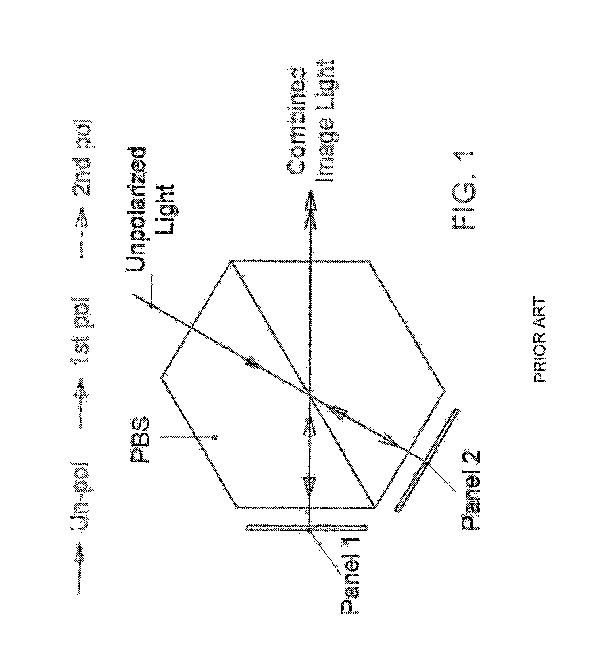
Although there are different types of polarizers or polarizing beam-splitters available today, each of them has limitations either due to poor performance, large device size, or high manufacturing cost, that prevents them from being widely used in applications such as 3D projection displays.
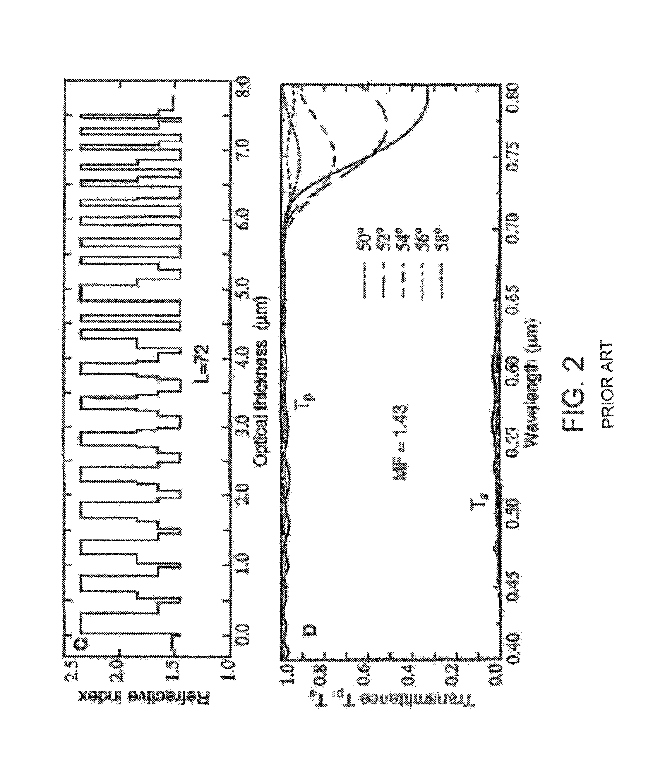
Although it has better performance than conventional MacNeille polarizers and other modified MacNeille polarizers, its performance still does not meet the requirement, especially in the angular field, for many applications including 3D projection displays.
The disadvantages of the Li Li PBS are, however, that the incident angles or operational angles are above the critical angle and larger than those of conventional or modified MacNeille polarizers because of the requirement of frustrated total internal reflection.
This results in larger prism sizes and consequently large size optical systems and higher cost which is not desirable in many applications.
Furthermore, the Li Li PBS preferably requires the use of high index prism substrates (preferably with index higher than 1.70) that need optical contacting due to the unavailability of suitable high refractive index optical glues, this also results in high manufacturing cost.

Method used


Image

  • Polarizing beam splitters
  • Polarizing beam splitters
  • Polarizing beam splitters

Examples


Embodiment Construction

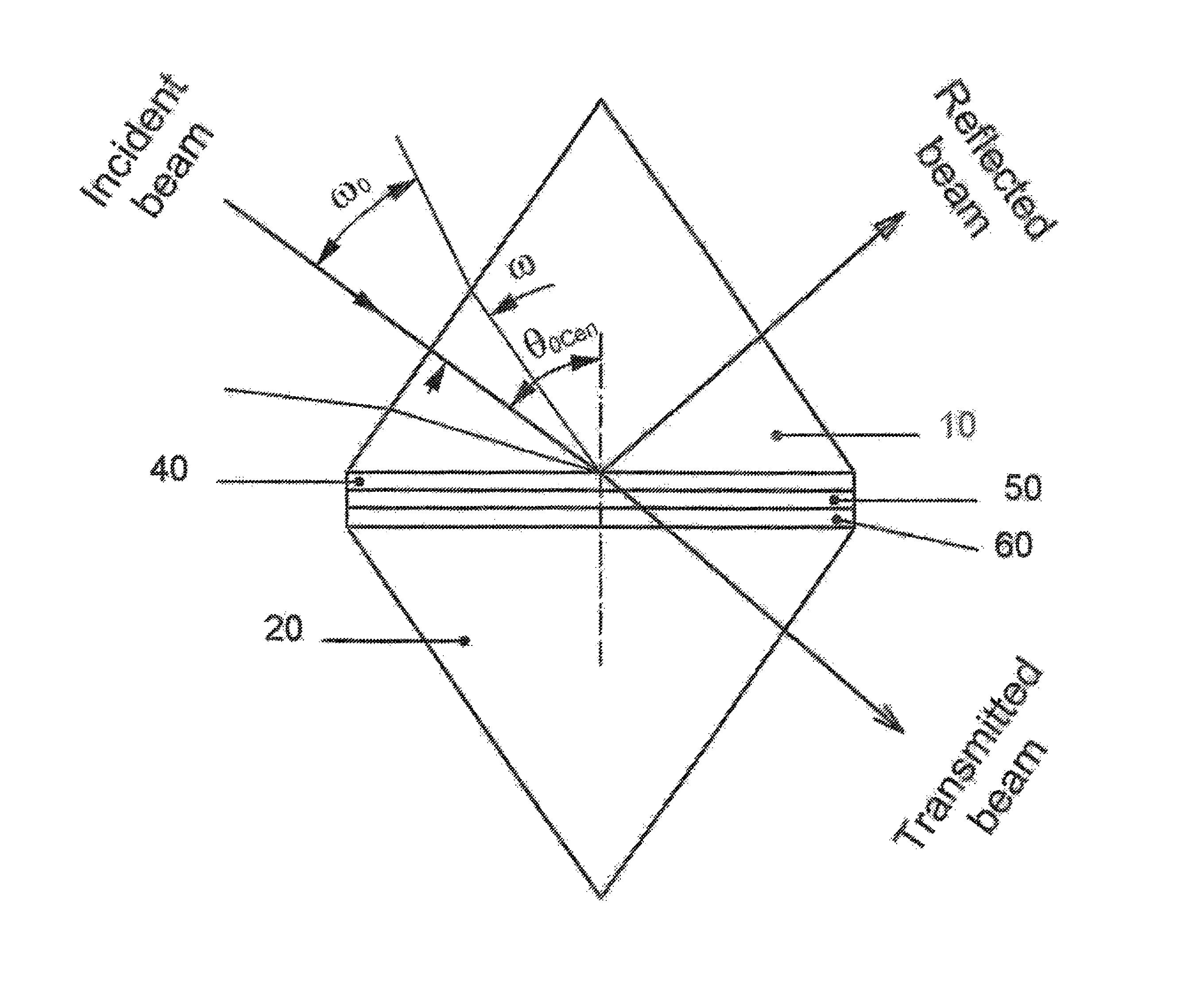
[0060]The polarizing beam-splitters in accordance with embodiments of the present invention shown in FIG. 3 each comprise of two transparent substrates 10 and 20 having a refractive index n0, the substrates are made of transparent material such as optical glasses, plastics or semiconductors; a thin film polarizing beam-splitter coating 40 sandwiched between the two transparent substrates providing a multilayer thin film structure; an optional transparent glue layer 50 with a refractive index nS and an optional anti-reflection (AR) coating 60. The multilayer thin film structure 40 consists of plural thin film layers having layer thickness d1, . . . , di, . . . , dm, and reflective indices n1, . . . , ni, . . . , nm, where m represents the total number of layers and the refractive indices include a highest refractive index nH, a lowest refractive index nL, and at least one middle refractive index nA and nL0. Any two adjacent layers with different refractive indices form a layer interf...


PUM


Abstract

A polarizing beam splitter has a pair of opposed transparent prism substrates with a refractive index n0, and providing at least one input port and at least one output port. The input port accepts light incident over a range of operational angles including a central operational angle. A multilayer thin film structure is sandwiched between the pair of opposed transparent substrates and consists essentially of a plurality of layers l1 . . . lm having respective refractive indices n1 . . . nm, wherein at least three of said refractive indices n1 . . . nm are different, and wherein the refractive index of the substrates n0 lies between the highest refractive index nH and lowest refractive index nL, and wherein nH, nL and n0 define a Brewster angle θ0B:θ0⁢B=arcsin(nL⁢nHn0⁢nL2+nH2),anda critical angle θc:θC=arcsin⁡(nLn0).The refractive indices n0 and n1 . . . nm are selected such that the central operational angle for a beam incident on the multiple thin film structure lies above the Brewster angle θ0B and such that most or all the operational angles defined by said input port lie above the Brewster angle θ0B. For p-polarized light at least one optical admittance of the layers with refractive indices n1 . . . nm is lower or very close to that of the optical admittance of the substrate for the operational angles such that the thin film polarizing beam-splitter favors the transmittance for p-polarized light incident at that input port such that most of the p-polarized light is transmitted through the multiple thin film structure. For s-polarized light the polarizing beam-splitter acts as a high reflective coating to favor the reflectance for s-polarized light incident at the input port such that most of the s-polarized light is reflected from said multiple thin film structure. The polarizing beam splitter is compact and yet remains functional over a wide range of operational angles.

Description

REFERENCE TO CROSS-RELATED APPLICATIONS[0001]This application claims the benefit under 35 USC 119(e) of U.S. provisional application No. 61 / 085,817, filed Aug. 1, 2008, the contents of which are herein incorporated by reference.FIELD OF THE INVENTION[0002]This invention relates to polarizing beam-splitters (PBS), and more particularly, to thin film interference based polarizing beam-splitters for separating or combining polarized light.BACKGROUND OF THE INVENTION[0003]Polarizing beam-splitters are used for many applications to physically separate or combine polarized light in two orthogonal polarizations, by transmitting light in one polarization state and reflecting light in the other polarization state. The useful properties of a PBS are often described as the operational wavelength range or bandwidth, the angular field or the operational angular range, the average extinction ratios (the ratio of the light intensities of desired polarization over the undesired polarization) in bot...

Claims


Application Information

Patent Timeline
IPC IPC(8): G02B27/28G02B5/30
CPCG02B27/28G02B5/30G02B27/283
Inventor BOOTHROYD, SIMON ANDREWDOBROWOLSKI, JERZY ADAM
Owner BOOTHROYD SIMON ANDREW
Learn More