Liquid crystal display

a liquid crystal display and display technology, applied in non-linear optics, instruments, optics, etc., can solve the problems of blocking off a view in the narrow viewing angle mode, and not giving rise to sufficient effect, so as to achieve efficient narrowing the viewing angle

Inactive Publication Date: 2009-04-16
SHARP KK
View PDF25 Cites 10 Cited by
  • Summary
  • Abstract
  • Description
  • Claims
  • Application Information

AI Technical Summary

Benefits of technology

[0016]This allows the first lens sheet having a vertically-stripped prism ridgeline pattern to collect light emitted from the backlight so that the viewing angle can be narrowed in the horizontal direction. The above arrangement further allows the second lens sheet having a horizontally-stripped prism ridge pattern to collect light emitted from the backlight so that the viewing angle can be narrowed in the vertical direction.
[0017]As a result, it is possible to efficiently narrow the viewing angle both in the horizontal and vertical directions with the use of the first and second lens sheets.

Problems solved by technology

However, this does not give rise to sufficient effect.
However, a decrease in contrast to such a degree causes a display to be sufficiently visible to a person next to the user.
However, this does not give rise to sufficient effect, either.
However, according to such a method, blocking off of a view in the narrow viewing angle mode is not sufficient in the wide viewing angle direction, i.e., in a direction in which the narrow viewing angle is not realized.
This is likely to cause a problem that a display may be seen by other people.

Method used


Image

  • Liquid crystal display
  • Liquid crystal display
  • Liquid crystal display

Examples


embodiment 1

[0071]One embodiment of the present invention is described below with reference to FIGS. 1 through 12. For convenience of explanation, the drawings which are referred to in the following description only show, in a simplified manner, main members which are needed for explanation of the present invention, among the constituent members of one embodiment of the present invention. As such, a liquid crystal display of the present invention may include any constituent member which is not shown in the drawings that are referred to in the present specification. In addition, the sizes of members in the figures do not accurately show the sizes of the actual constituent members, the size proportion of such members, or the like.

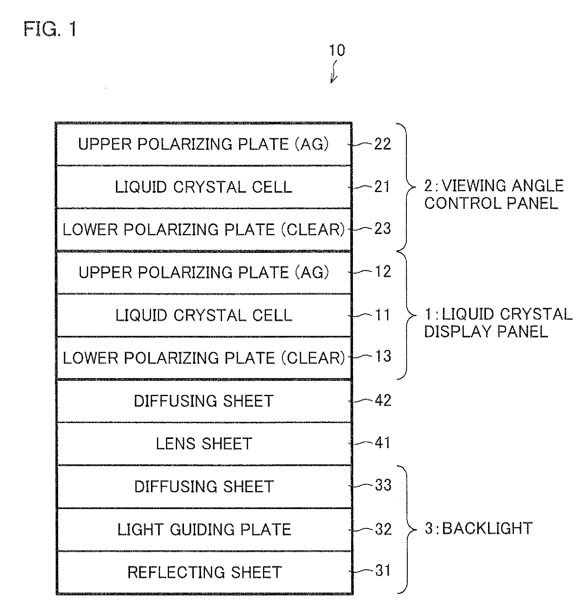
[0072]The following description deals with an arrangement of a liquid crystal display 10 of the present embodiment, with reference to FIG. 1. FIG. 1 is a sectional view schematically illustrating an arrangement of the liquid crystal display 10.

[0073]As shown in FIG. 1, t...

embodiment 2

[0120]Another embodiment of the present invention is described below with reference to FIGS. 13 through 16. Note that the arrangement that is not described in Embodiment 2 is the same as in Embodiment 1, and that, for convenience of explanation, same members in Embodiment 2 as those in Embodiment 1 are assigned the same reference numerals and the description of the members is omitted.

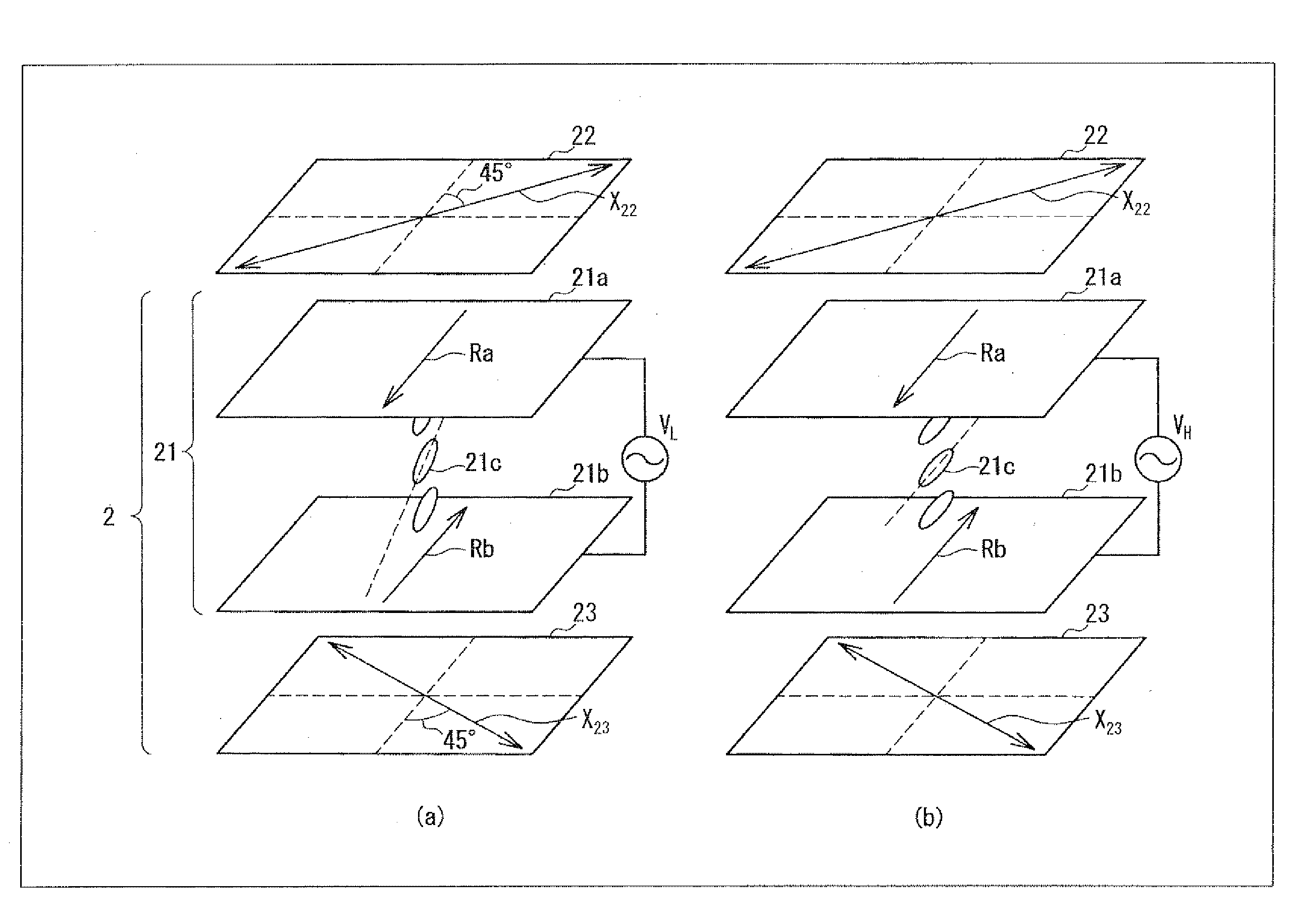
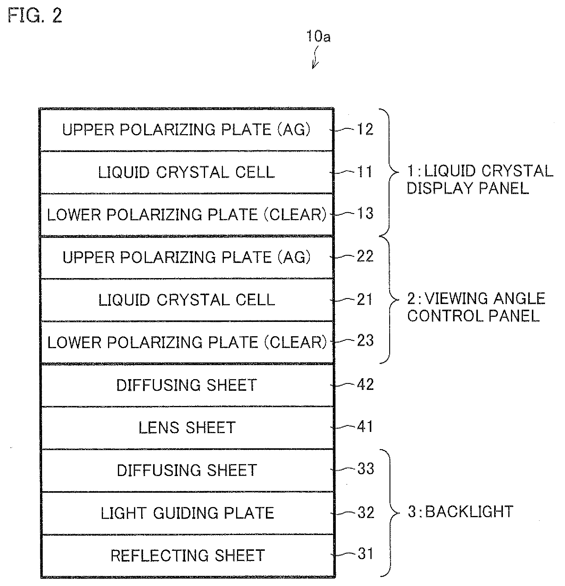
[0121]As shown in FIG. 13, a liquid crystal display 50 of the present embodiment is arranged such that, as contrasted to the liquid crystal display 10 of Embodiment 1, neither a upper polarizing plate 12 for the liquid crystal panel nor a lower polarizing plate 23 for the control panel has been subjected to a diffusion treatment (shown in FIG. 13 as “UPPER POLARIZING PLATE (CLEAR) 12” and “LOWER POLARIZING PLATE (CLEAR) 23”, respectively). However, the present embodiment is not necessarily limited to this. For example, it may be arranged such that a single polarizing plate, which has not been subjected ...

embodiment 3

[0129]A further embodiment of the present invention is described below with reference to FIGS. 17 through 19. Note that the arrangement that is not described in Embodiment 3 is the same as in Embodiment 1, and that, for convenience of explanation, same members in Embodiment 3 as those in Embodiment 1 are assigned the same reference numerals and the description of the members is omitted.

[0130]In each of the liquid crystal displays 50 and 50a of Embodiment 2, polarizing plates, which have not been subjected to a diffusion treatment, are included between the liquid crystal cell 11 of the liquid crystal display panel 1 and the liquid crystal cell 21 of the viewing angle control panel 2, in addition to either the lens sheet 41 or the first lens sheet 41a and the second lens sheet 41b.

[0131]However, the present invention is not necessarily limited to this. The effect of narrowing a viewing angle is brought about by an arrangement in which polarizing plates, which have not been subjected ...


PUM

PropertyMeasurementUnit
twist angleaaaaaaaaaa
voltageaaaaaaaaaa
voltageaaaaaaaaaa

Abstract

A liquid crystal display includes a backlight (3), a liquid crystal display panel (1), and a viewing angle control panel (2) for controlling the viewing angle of the display panel (1), the liquid crystal display further including a lens sheet (41) provided between the backlight (3) and the liquid crystal display panel (1). This provides a display device system which is capable of providing better blocking.

Description

TECHNICAL FIELD[0001]The present invention relates to a liquid crystal display which includes a viewing angle control panel for controlling the viewing angle of a display panel.BACKGROUND ART[0002]Display devices are generally required to have as wide a viewing angle as possible so that a clear image can be seen from any angle. Various technological developments have been carried out in connection with widening of the viewing angle of liquid crystal display devices. This is particularly because liquid crystal display devices, which have been in widespread use in recent years, include liquid crystal having viewing angle dependence.[0003]However, a narrow viewing angle may be preferable, in a specific use environment. This allows a display content to be visible only to the user. Furthermore, electronic devices such as laptop personal computers, personal data assistants (PDAs), and portable phones are particularly likely to be used in sites, where the general public may be present, suc...

Claims


Application Information

Patent Timeline
Patent Type & Authority Applications(United States)
IPC IPC(8): G02F1/1335G02F1/13357
CPCG02F1/1323G02F2001/133607G02F1/1347G02F1/133607G02F1/1335G02F1/1333
Inventor SAKAI, TAKEHIKOOKAZAKI, TSUYOSHIMORISHITA, KATSUHIKOKATAOKA, YOSHIHARUTSUKAMURA, CHIKANORICHIBA, DAI
Owner SHARP KK
Why Eureka
Try Eureka