
Liquid crystal display device satisfying relationship between characteristics of liquid crystal panel and diffusing layer

a liquid crystal display device and characteristic relationship technology, applied in non-linear optics, instruments, optics, etc., can solve the problems of deteriorating contrast-versus-viewing angle characteristics, transflective liquid crystal display devices combined with forward-scattering films transflective liquid crystal display devices have problems of narrow viewing angles for transmissive displays, etc., to achieve bright display and high image quality display

Active Publication Date: 2006-02-14
BOE TECH GRP CO LTD
View PDF10 Cites 3 Cited by
  • Summary
  • Abstract
  • Description
  • Claims
  • Application Information

AI Technical Summary

Benefits of technology

[0007]In view of high image quality or cost reduction of liquid crystal display devices, the technologies described above are effective, and moreover, by combining them, a high-image-quality liquid crystal display device may be provided at lower cost. However, it was found that such combinations deteriorate the contrast-versus-viewing-angle characteristics particularly for transmissive display.
[0008]In view of these circumstances, it is an object of the invention to provide a high-image-quality, wide-viewing-angle liquid crystal display device that can be manufactured at low cost, and to provide an electronic apparatus provided with such a liquid crystal display device.
[0009]Transflective liquid crystal display devices combined with forward-scattering films have problems of narrow viewing angles, which may be caused particularly as in the following. Firstly, transflective liquid crystal display devices have had a problem of narrow viewing angles for transmissive display. This is due to the fact that a transflective film is provided on the inner surface of the liquid crystal panel for preventing parallax errors, thus restricting the operation of the reflective display to the use of only a single polarizer provided adjacent to the viewer. This inevitably reduces the flexibility for optical layout.

Problems solved by technology

However, it was found that such combinations deteriorate the contrast-versus-viewing-angle characteristics particularly for transmissive display.
Transflective liquid crystal display devices combined with forward-scattering films have problems of narrow viewing angles, which may be caused particularly as in the following.
Firstly, transflective liquid crystal display devices have had a problem of narrow viewing angles for transmissive display.
This is due to the fact that a transflective film is provided on the inner surface of the liquid crystal panel for preventing parallax errors, thus restricting the operation of the reflective display to the use of only a single polarizer provided adjacent to the viewer.
This inevitably reduces the flexibility for optical layout.
Secondly, in a transflective liquid crystal display device having a forward-scattering film, although visual improvement by light diffusion is achieved for reflective display, light beams for transmissive display are also similarly diffused.
Consequently, the black level of the liquid crystal display device is increased, thus lowering the contrast.
For this reason, in addition to the narrow viewing angle, an application of a forward-scattering film to a transflective liquid crystal display device also deteriorates the contrast-versus-viewing-angle characteristics and lowers the display quality significantly.

Method used


Image

  • Liquid crystal display device satisfying relationship between characteristics of liquid crystal panel and diffusing layer
  • Liquid crystal display device satisfying relationship between characteristics of liquid crystal panel and diffusing layer
  • Liquid crystal display device satisfying relationship between characteristics of liquid crystal panel and diffusing layer

Examples


Embodiment Construction

[0037]An embodiment of the invention will now be described with reference to the drawings.

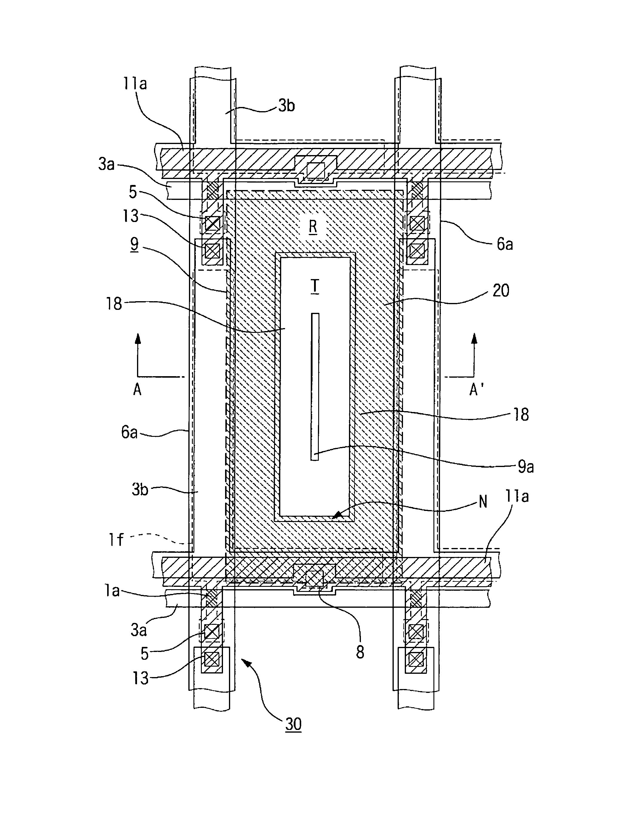
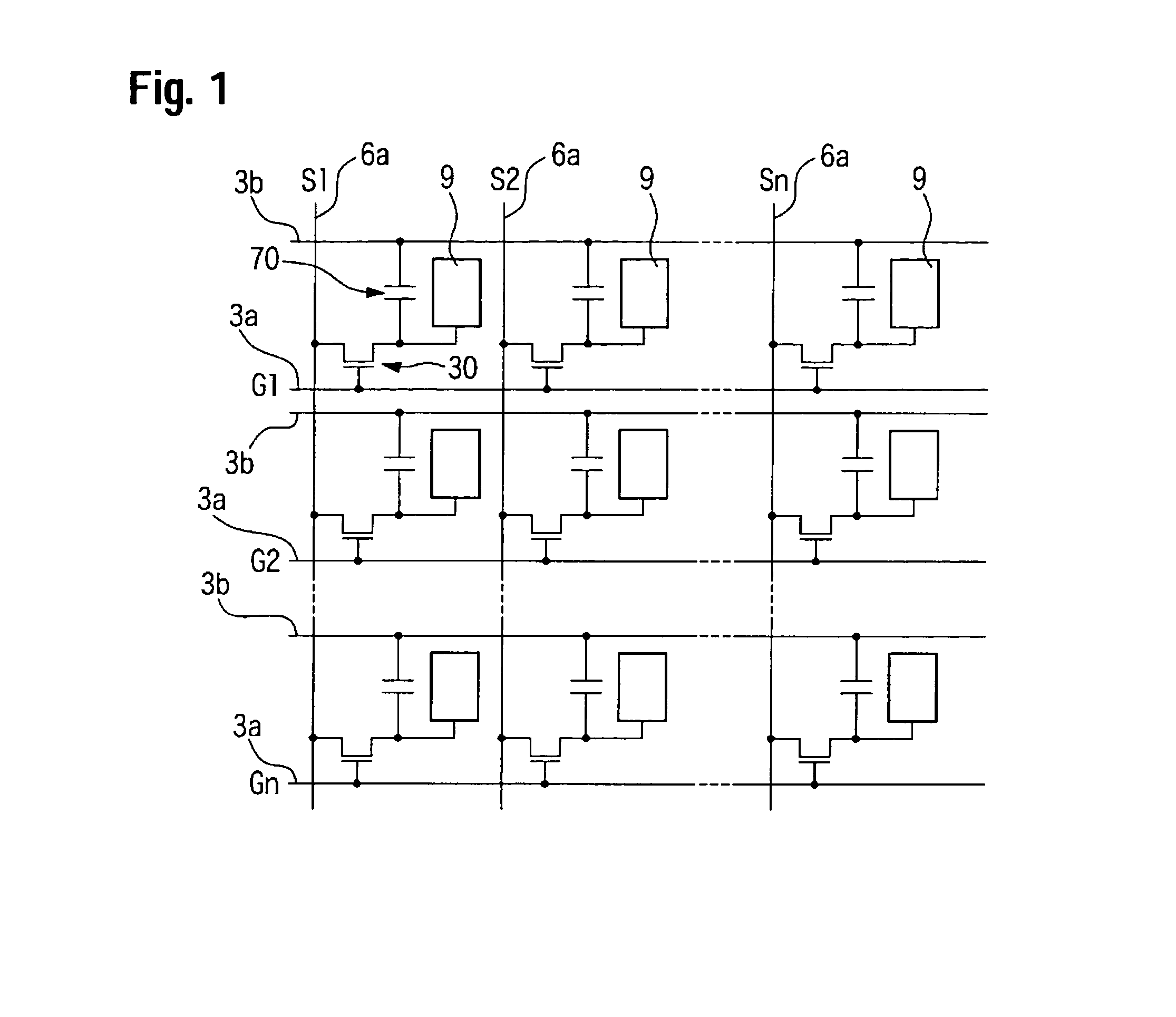
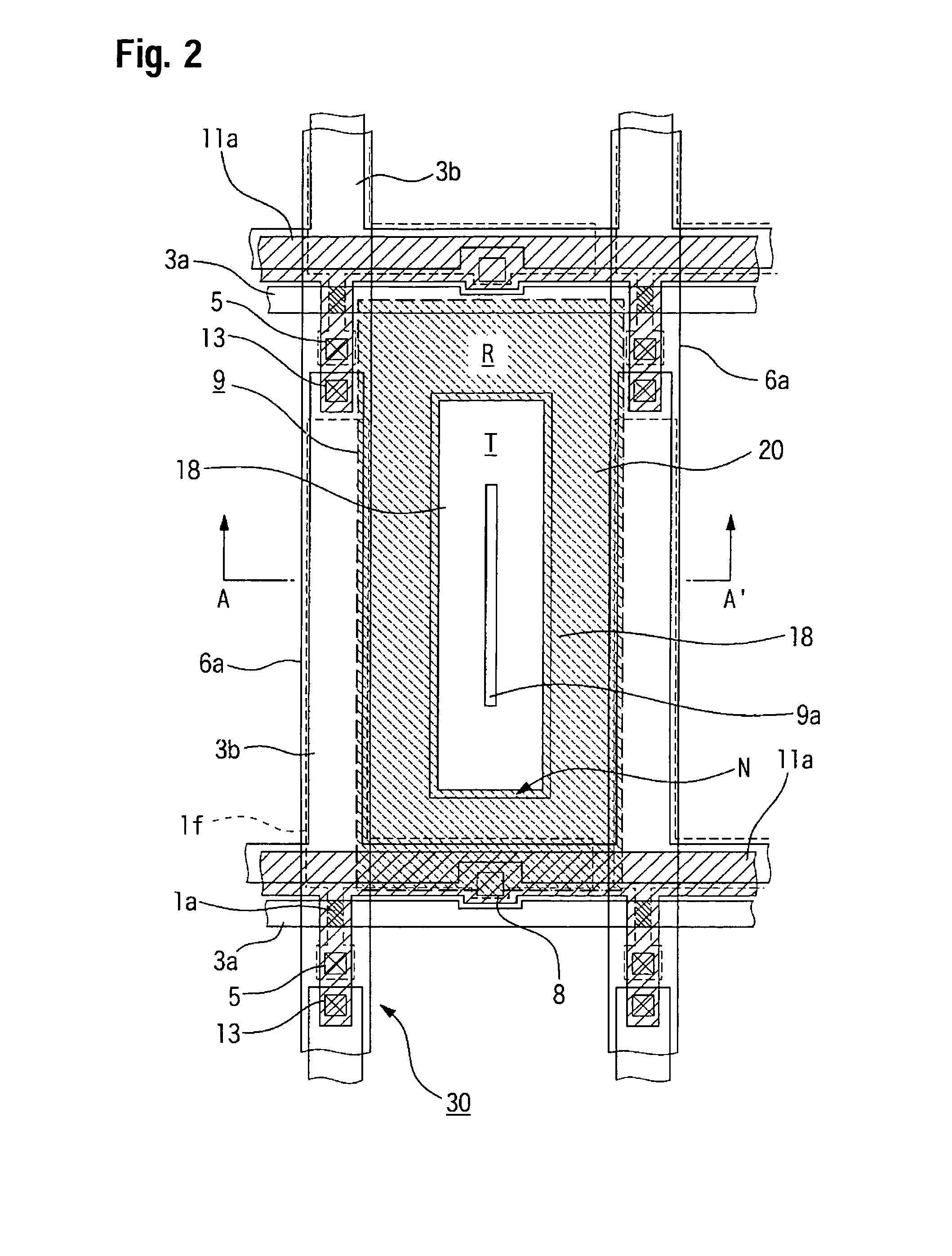
[0038]A liquid crystal display device of this embodiment is an example of an active-matrix liquid crystal display device employing thin film transistors (TFTs) as switching elements. FIG. 1 is an equivalent circuit diagram having a plurality of dots arranged in a matrix forming an image display region of the liquid crystal display device according to this embodiment. FIG. 2 is a plan view illustrating the structure of one of the dots on a TFT-array substrate. FIG. 3 is a partial cross-sectional view taken along line A—A′ of FIG. 2. In each of the drawings, each layer and component is shown at a different scale to improve viewability.

[0039]Referring to FIG. 1, in the liquid crystal display device of this embodiment, the plurality of dots arranged in a matrix forming the image display region are each provided with a pixel electrode 9 and a TFT 30 which acts as a switching element for controlling ...


PUM


Abstract

The invention provides a high-image-quality, wide-viewing-angle liquid crystal display device that can be manufactured at low cost, and to provide an electronic apparatus provided with such a liquid crystal display device. A liquid crystal display device of the invention can include an upper substrate and a lower substrate which are disposed facing each other, a liquid crystal layer interposed between the upper substrate and the lower substrate, an upper polarizer and a lower polarizer which are separated by the liquid crystal layer and are disposed adjacent to two opposite sides of the liquid crystal layer, and a liquid crystal panel having dot regions each provided with a transmissive display area and a reflective display area. One of the upper substrate and the lower substrate can be provided with a liquid-crystal-layer thickness adjustment layer on a side of the substrate adjacent to the liquid crystal layer. This liquid-crystal-layer thickness adjustment layer provides different thicknesses for the liquid crystal layer in the transmissive display area and the reflective display area. The upper substrate has a light-diffusing layer disposed adjacent to the outer surface of the upper substrate. A half-width α for the contrast-versus-viewing-angle characteristics of the liquid crystal panel and a half-width β for the diffusion characteristics of the light-diffusing layer satisfy the relationship α≧3β.

Description

BACKGROUND OF THE INVENTION[0001]1. Field of Invention[0002]The present invention relates to liquid crystal display devices and electronic apparatuses.[0003]2. Description of Related Art[0004]Transflective liquid crystal display devices, which are provided with dot regions each having a reflective display area and a transmissive display area, have both reflective and transmissive functions and are thus capable of switching between display modes depending on the ambient brightness. Such transflective liquid crystal display devices are suitable for displays in portable apparatuses since these devices have low power consumption and are capable of providing a high-quality display even in dark surroundings. Particularly in recent years, portable apparatuses are becoming more and more common and are continuously being developed to have high performance, and for this reason, further demands for high image quality as well as cost reduction for transflective liquid crystal display devices ar...

Claims


Application Information

Patent Timeline
IPC IPC(8): G02F1/1335G02F1/1333
CPCG02F1/133371G02F1/133504G02F2203/09G02F1/133707G02F1/1335
Inventor MAEDA, TSUYOSHI
Owner BOE TECH GRP CO LTD
Learn More