Surveillance camera system

a surveillance camera and camera body technology, applied in closed circuit television systems, color television details, television systems, etc., can solve the problems of inability to deal with artificial or unexpected changes, difficult to get adequate image information, and prone to extend over the full screen, so as to improve the functions of the surveillance camera system, increase the image size of the subject, and widen the shooting area

Active Publication Date: 2015-04-07
FUJIFILM CORP
View PDF33 Cites 3 Cited by
  • Summary
  • Abstract
  • Description
  • Claims
  • Application Information

AI Technical Summary

Benefits of technology

[0008]The invention has been made in view of the above circumstances, and it is an object of the invention to provide a surveillance camera system capable of taking a shot in a local area at proper exposure not to be affected by exposure control of the overall shooting area when a local area that needs particularly detailed surveillance exists in a shooting area as a target of surveillance.
[0011]Also, in order to enhance functions of the surveillance camera system, it is effective to use a second area surveillance camera which has a focal length different from that of the area surveillance camera or those of the camera modules, and which is focused for a second shooting distance different from the first shooting distance, a shooting magnification of the second area surveillance camera focused for the second shooting distance being substantially equal to that of the area surveillance camera focused for the first shooting distance.
[0012]According to the above configuration, the area surveillance camera and the local camera take a shot individually. Therefore, the exposure control for one of the area surveillance camera and the local camera does not influence on the exposure control for the other at all. If the angle of view of the local camera is narrow sufficiently in view of an image size of the target of surveillance, such a situation can be prevented that even if automatic exposure control is applied based on the screen average metering, the target of surveillance is extremely overexposed or underexposed. Also, when an image captured by the area surveillance camera and an image captured by the local camera are displayed in parallel or both images are combined and displayed on the monitor, the target of surveillance can have the same image size. Therefore, the easy-observe screen display can be obtained. When the area surveillance camera includes the plurality of camera modules, an image size of the subject can be increased while keeping a wide shooting area. When the second area surveillance camera is used together, the image of the subject can be captured clearly with the second shooting distance different from the first shooting distance at another magnification. Also a surveillance effect can be enhanced.

Problems solved by technology

On the other hand, when great variation of brightness is caused in a part of the shooting area, its influence is prone to extend over the full screen.
Therefore, this exposure control system has such a problem that since an original target of surveillance is overexposed or underexposed, it becomes difficult to get adequate image information.
However, the approach disclosed in JP 2001-211383 A is effective for a previously expected environmental change such as change in a solar position, change in weather, or the like, but cannot deal with an artificial or unexpected change.
Thus, image processing becomes complicated and a processing time is prolonged.
Therefore, a follow-up performance also becomes an issue in the case where the brightness of a part of the shooting screen is changed within a short time.
Thus, there is a drawback in the viewpoint of versatility.

Method used


Image

  • Surveillance camera system
  • Surveillance camera system
  • Surveillance camera system

Examples


Embodiment Construction

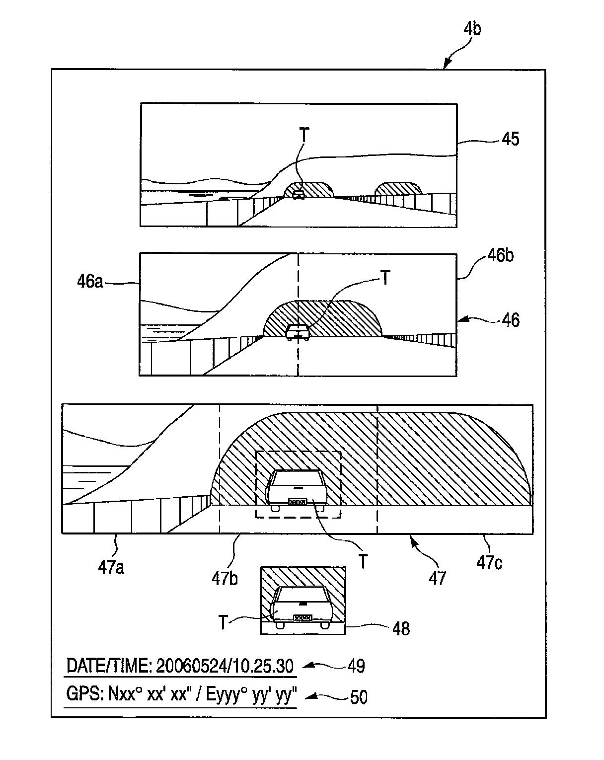
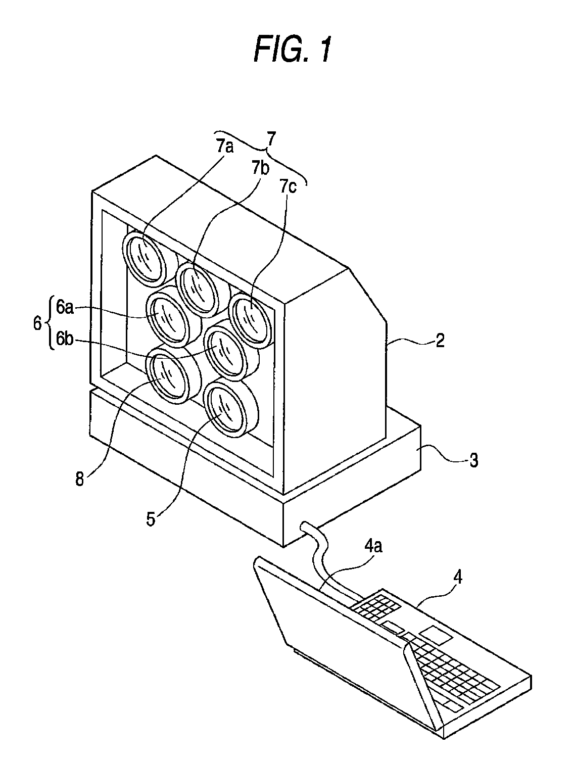
[0020]As an embodiment of the invention, an external appearance of a surveillance camera system used for the purpose of conducting surveillance over a vehicle running on the road is shown in FIG. 1. This camera system includes a shooting unit 2, a control unit and a mobile personal computer 4. The control unit 3 controls driving of plural types of cameras or camera modules incorporated into the shooting unit 2 and has a built-in recording device for recording obtained image data. The mobile personal computer 4 is connected to the control unit 3. An image is displayed on a monitor 4a of the personal computer 4 based on an edited image signal output from the control unit 3. In this case, a dedicated monitor may be connected for image display instead of the personal computer 4.

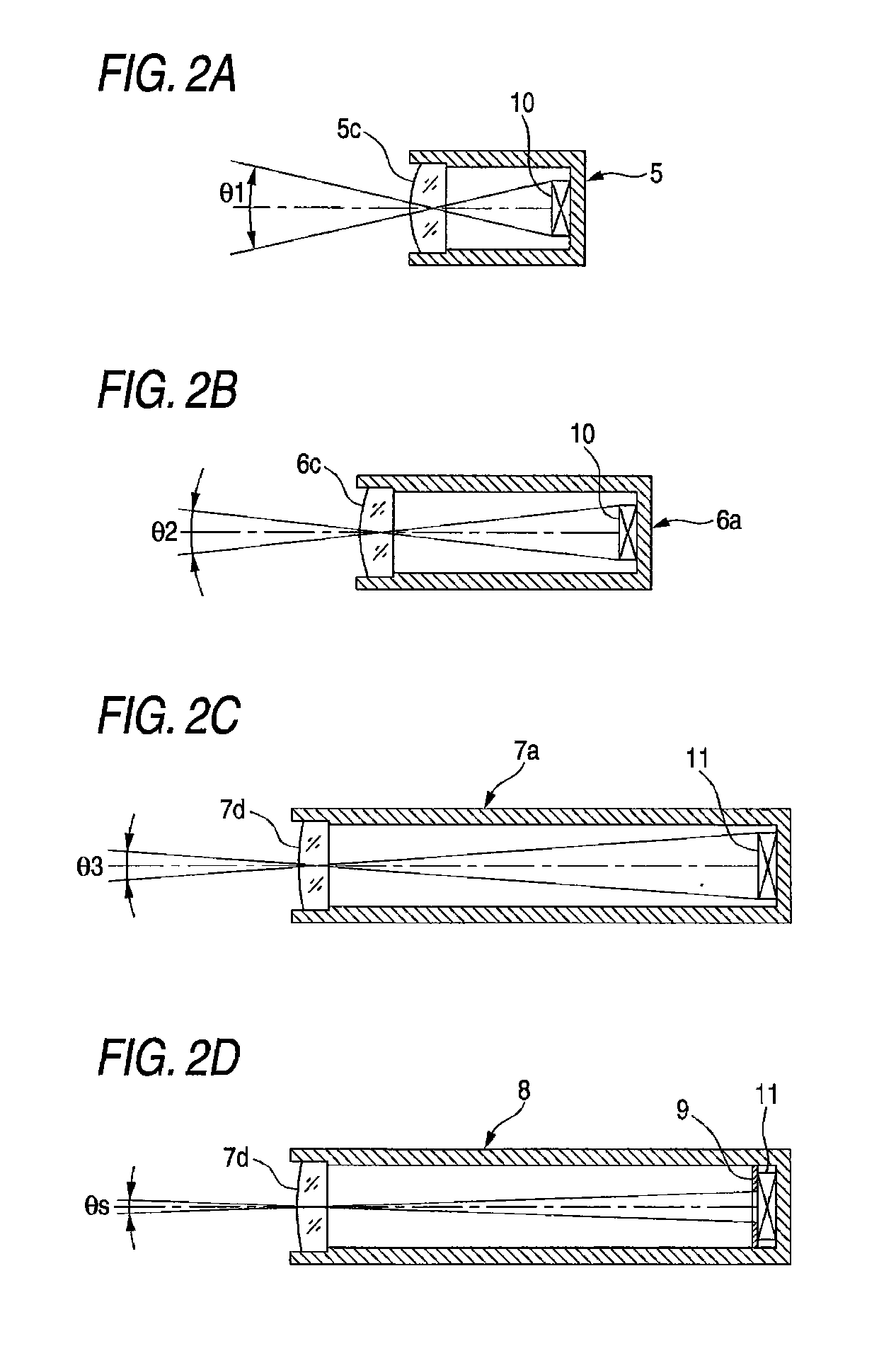
[0021]The shooting unit 2 and the control unit 3 are fitted to an interior of a car via a support device that has a shock absorbing action. Various types of cameras incorporated into the shooting unit 2 take a sh...


PUM


Abstract

A surveillance camera system includes a first camera 5 having an angle of view θ1, a second camera 6 which is a combination of two camera modules 6a, 6b each having an angle of view θ2, a third camera 7 which is a combination of three camera modules 7a, 7b, 7c each having an angle of view θ3, and a local camera 8 having an angle of view θs. The first to third cameras 5 to 7 act as area surveillance cameras to which the optimum shooting distance is set, respectively. The local camera 8 takes a shot of a local area, which is set in a shooting area of the third camera 7, at the narrowest angle of view θs. The respective cameras take a shot individually under automatic exposure control.

Description

CROSS-REFERENCE TO RELATED APPLICATIONS[0001]This application is based upon and claims the benefit of priority from the Japanese Patent Application No. 2006-235885 filed on Aug. 31, 2006, the entire contents of which are incorporated herein by reference.BACKGROUND OF THE INVENTION[0002]1. Technical Field[0003]The invention relates to a surveillance camera system using a plurality of cameras and, more particularly, a surveillance camera system capable of preventing such a situation that captured information of a particularly important local area in a shooting area is lost due to overexposure / underexposure while continuing the shooting under automatic exposure control.[0004]2. Description of the Related Art[0005]As a camera for use in surveillance, normally a digital camera having an automatic exposure controlling function is used. Exposure control is made such that an integrated brightness level in the overall shooting area is set properly. Control of an exposure value is made by adj...

Claims


Application Information

Patent Timeline
Patent Type & Authority Patents(United States)
IPC IPC(8): H04N7/18G08G1/04H04N5/232H04N5/235H04N5/247
CPCH04N7/18G08G1/04H04N5/23212H04N5/2355H04N5/247H04N23/673H04N23/635H04N23/741H04N23/90
Inventor TANAKA, YASUNORI
Owner FUJIFILM CORP
Why Eureka
Try Eureka