
Image processing of an incoming light field using a spatial light modulator

a technology of spatial light and light modulator, applied in the field of image processing of an incoming light field using a spatial light modulator, can solve the problems of creating dangerous situations, significantly impaired vision, and limited instantaneous sensitivity of the human eye, so as to reduce the brightness or contrast, reduce the time required, and reduce the brightness of higher-luminance objects

Active Publication Date: 2009-04-16
NVIDIA CORP
View PDF99 Cites 20 Cited by
  • Summary
  • Abstract
  • Description
  • Claims
  • Application Information

AI Technical Summary

Benefits of technology

[0004]Accordingly, a need exists to reduce the time required for the human eye to adjust to luminance changes in an incoming light field. Additionally, a need exists to reduce the brightness of higher-luminance objects without significantly reducing the brightness or contrast of objects with lower luminance of the same field of view. Embodiments of the present invention provide novel solutions to these needs and others as described below.

Problems solved by technology

However, the instantaneous sensitivity of the human eye is far more limited.
Human vision is significantly impaired during large-scale adaptations which can take seconds or even minutes, thereby causing inconvenience and creating dangerous situations when driving automobiles or engaging in other dangerous activities.
However, poorly-lit objects or scenes are also darkened by such glasses and goggles, which can increase the danger in certain situations.
For example, ski or snowboard goggles can further reduce the brightness of shaded terrain features, which can lead to injury or even death due to miscalculation when maneuvering, unawareness of a given feature, or the like.
Also, tinted sunglasses worn when driving on a sunny day may make shaded objects or portions of roadway harder to see, thereby leading to automobile damage and / or personal injury due to loss of control of the vehicle, collision, or the like.

Method used


Image

  • Image processing of an incoming light field using a spatial light modulator
  • Image processing of an incoming light field using a spatial light modulator
  • Image processing of an incoming light field using a spatial light modulator

Examples


Embodiment Construction

[0027]Reference will now be made in detail to embodiments of the present invention, examples of which are illustrated in the accompanying drawings. While the present invention will be discussed in conjunction with the following embodiments, it will be understood that they are not intended to limit the present invention to these embodiments alone. On the contrary, the present invention is intended to cover alternatives, modifications, and equivalents which may be included with the spirit and scope of the present invention as defined by the appended claims. Furthermore, in the following detailed description of the present invention, numerous specific details are set forth in order to provide a thorough understanding of the present invention. However, embodiments of the present invention may be practiced without these specific details. In other instances, well-known methods, procedures, components, and circuits have not been described in detail so as not to unnecessarily obscure aspect...


PUM


Abstract

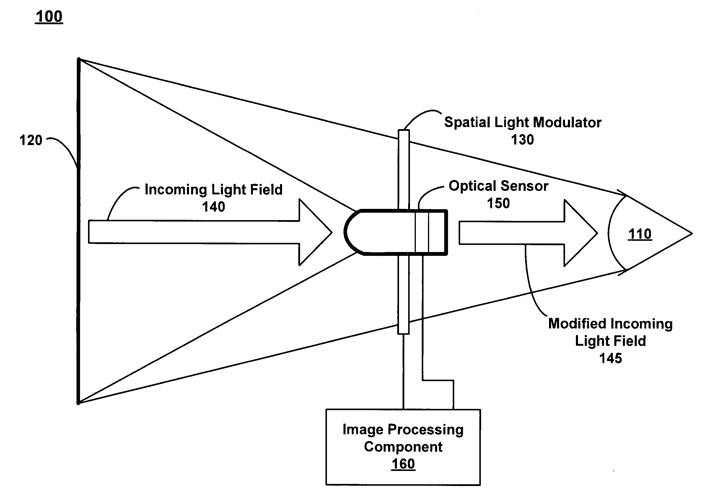
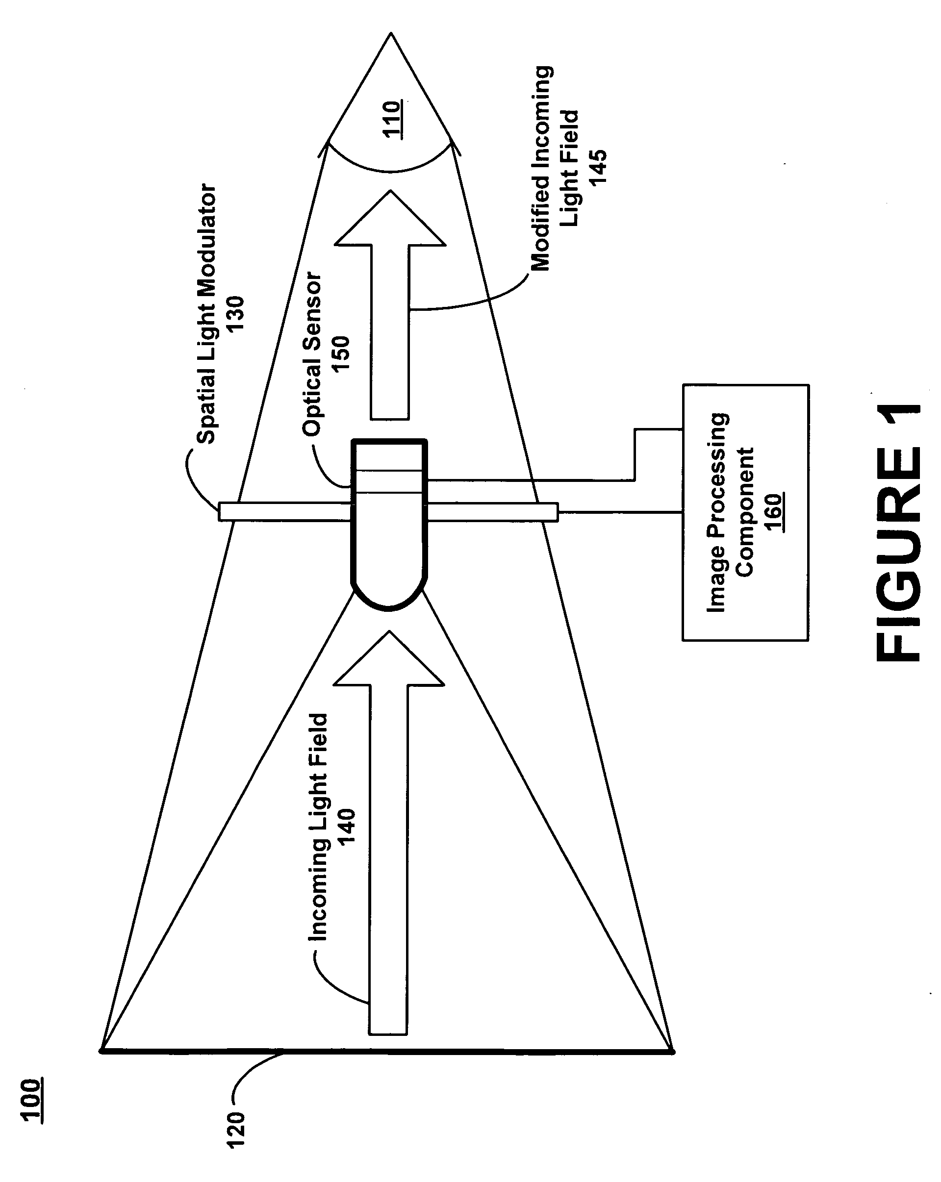
A method, computer-usable medium and a system for varying an incoming light field are disclosed. Embodiments provide mechanisms for performing image processing on an incoming light field using a spatial light modulator which is adjusted based upon characteristics of the incoming light field. The spatial light modulator may be positioned between the viewed scene and the eye, and therefore, may be semi-transparent. The image processing may consist of tone mapping, color enhancement, beautification, edge enhancement, spectral separation of colors, spectral separation of metamers, object emphasis, other image processing, or some combination thereof. Additionally, embodiments compensate for parallax errors by adjusting the spatial light modulator based upon the position of an observer with respect to the spatial light modulator. And further, embodiments may be incorporated into optical devices, wearable optical devices, windows, windshields, and the like, where the semi-transparent spatial light modulator adjusts the image before entering the eye.

Description

BACKGROUND OF THE INVENTION[0001]The human eye is a remarkable instrument which uses many adaptive mechanisms to enable sight in many different lighting conditions. For example, the eye can see as well in dim rooms as in full sunlight which is approximately one million times as bright. And as another example, the eye can even see with reduced acuity in starlit nights at luminance levels approximately fourteen levels of magnitude less than full sunlight.[0002]However, the instantaneous sensitivity of the human eye is far more limited. For example, at any moment the human eye can only perceive around 5 orders of magnitude of simultaneous contrast (equating to a luminance range or window of about 50,000:1 to 100,000:1), and as such, the human eye must shift its luminance window to adapt to new lighting conditions. Human vision is significantly impaired during large-scale adaptations which can take seconds or even minutes, thereby causing inconvenience and creating dangerous situations ...

Claims


Application Information

Patent Timeline
IPC IPC(8): G02F1/00G06K9/36
CPCG02B27/225G02B27/0093
Inventor LUEBKE, DAVID PATRICKHEIDRICH, WOLFGANG
Owner NVIDIA CORP
Learn More