
Torque Converter Control Method And Apparatus

Active Publication Date: 2009-04-16
GM GLOBAL TECH OPERATIONS LLC
View PDF12 Cites 11 Cited by
  • Summary
  • Abstract
  • Description
  • Claims
  • Application Information

AI Technical Summary

Benefits of technology

[0016]In another aspect of the invention, the lockup clutch includes a piston-actuated multi-plate clutch disposed between an apply chamber and a return chamber. The torque converter includes at least one check ball positioned within a

Problems solved by technology

Fuel efficiency may be reduced as a result of such slip, however, as only a portion of available engine power is utilized while operating under slip conditions.

Method used


Image

  • Torque Converter Control Method And Apparatus
  • Torque Converter Control Method And Apparatus
  • Torque Converter Control Method And Apparatus

Examples


Embodiment Construction

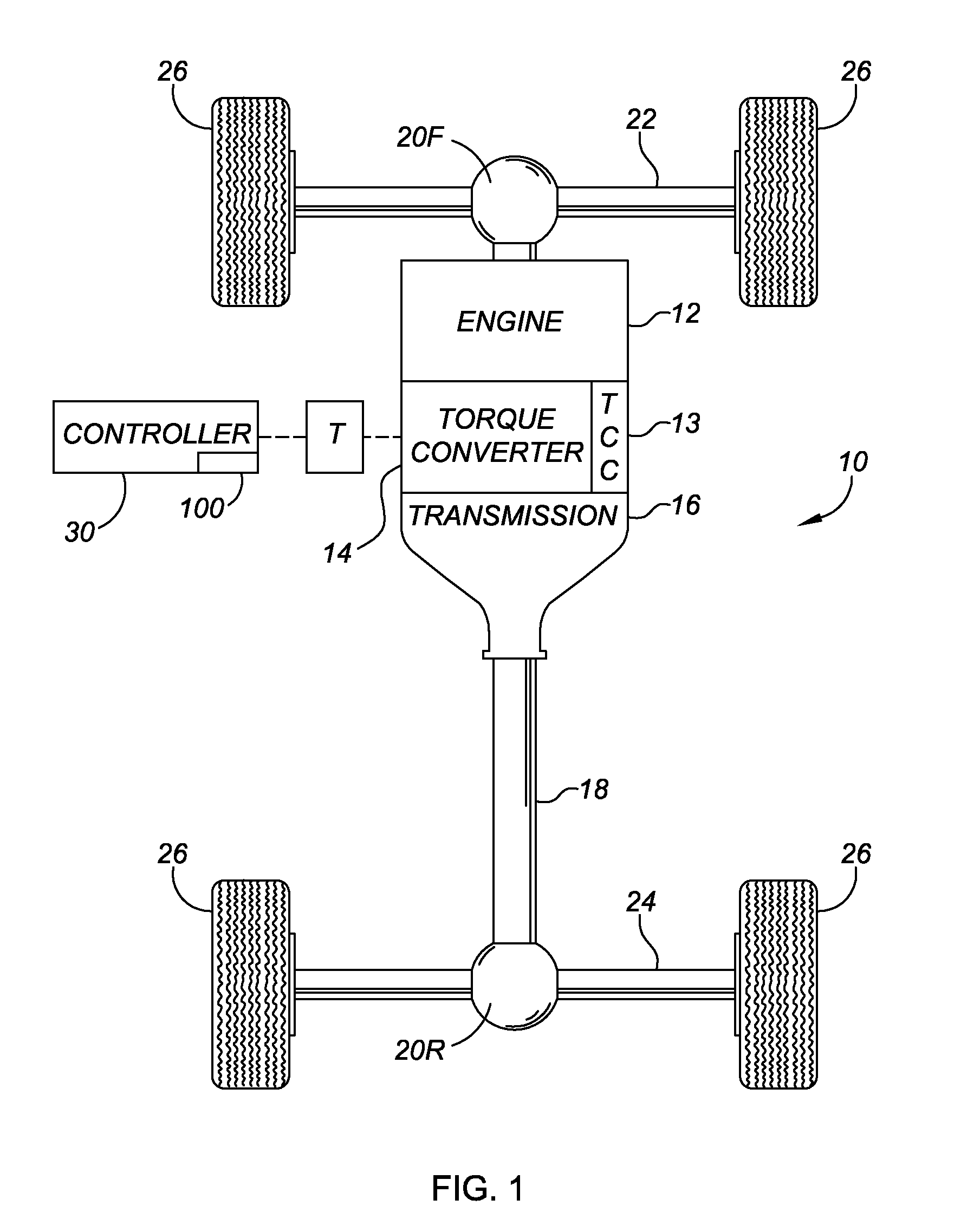
[0024]Referring to FIG. 1, wherein like reference numerals refer to like components, a vehicle 10 is shown having a plurality of wheels 26 disposed or positioned on a pair of axles 22 and 24. An energy conversion system or engine 12 is operatively connected to an automatic transmission 16 via a hydrodynamic torque converter assembly 14, referred to hereinafter for simplicity as converter 14. Transmission 16 has a rotatable input member (not shown) and a rotatable output member 18. Engine 12 is preferably a gasoline or diesel fuel engine, although alternative fuel-burning internal combustion engines, fuel cells, or other energy conversion systems capable of powering vehicle 10 may be usable within the scope of the invention.

[0025]Engine 12 is selectively connectable or engageable with the input member (not shown) of transmission 16 through converter 14. As will be understood by those of ordinary skill in the art, converter 14 is a hydrodynamic fluid coupling device operable for selec...


PUM


Abstract

A method for controlling a torque converter having an internal lockup clutch includes detecting vehicle operating conditions and executing one of a stored plurality of torque converter clutch modes each corresponding to a different set of vehicle operating conditions. A fully-released mode corresponds to vehicle pre-launch, a partially-engaged mode corresponds to post-launch of the vehicle in first gear, downshift, coasting, throttle tip-in, or throttle tip-out; a first fully-engaged mode corresponds to steady-state operation in second gear or a higher; and a second fully-engaged mode corresponds to an upshift. Slippage across the converter is controlled only during the first fully-engaged mode. A vehicle is also provided having an engine, transmission, torque converter with lockup clutch, and controller having a control algorithm. The algorithm executes a different lockup clutch mode based on the detected vehicle operating conditions, and the slippage across the converter is controlled during only one lockup clutch mode.

Description

TECHNICAL FIELD[0001]This invention relates generally to a method and apparatus for controlling the application of and a level of slippage across a torque converter clutch within a hydrodynamic torque converter assembly to thereby improve overall vehicle fuel economy.BACKGROUND OF THE INVENTION[0002]Automatic power transmissions used in modern vehicles typically include a multi-function hydrodynamic device commonly referred to as a torque converter. A torque converter is a fluid coupling device that automatically disengages a rotating engine crankshaft from a transmission input shaft during vehicle idling conditions to enable the vehicle to stop and / or to shift gears without stalling. Additionally, a torque converter may be used as a torque multiplier for multiplying engine torque in a lower vehicle speed range until the vehicle speed nearly matches engine speed.[0003]Within a torque converter, a pump, a turbine, and a stator combine to enable efficient fluid coupling of the rotatin...

Claims


Application Information

Patent Timeline
IPC IPC(8): F16H61/58G06F19/00
CPCF16H59/54F16H61/143Y10T477/635F16H2059/366F16H2061/145F16H2059/467
Inventor LEE, CHUNHAO J.SAMIE, FARZADKAO, CHI-KUAN
Owner GM GLOBAL TECH OPERATIONS LLC
Learn More