
Rebar Support Assembly

Inactive Publication Date: 2009-04-23
3GM PRODS
View PDF16 Cites 30 Cited by
  • Summary
  • Abstract
  • Description
  • Claims
  • Application Information

AI Technical Summary

Benefits of technology

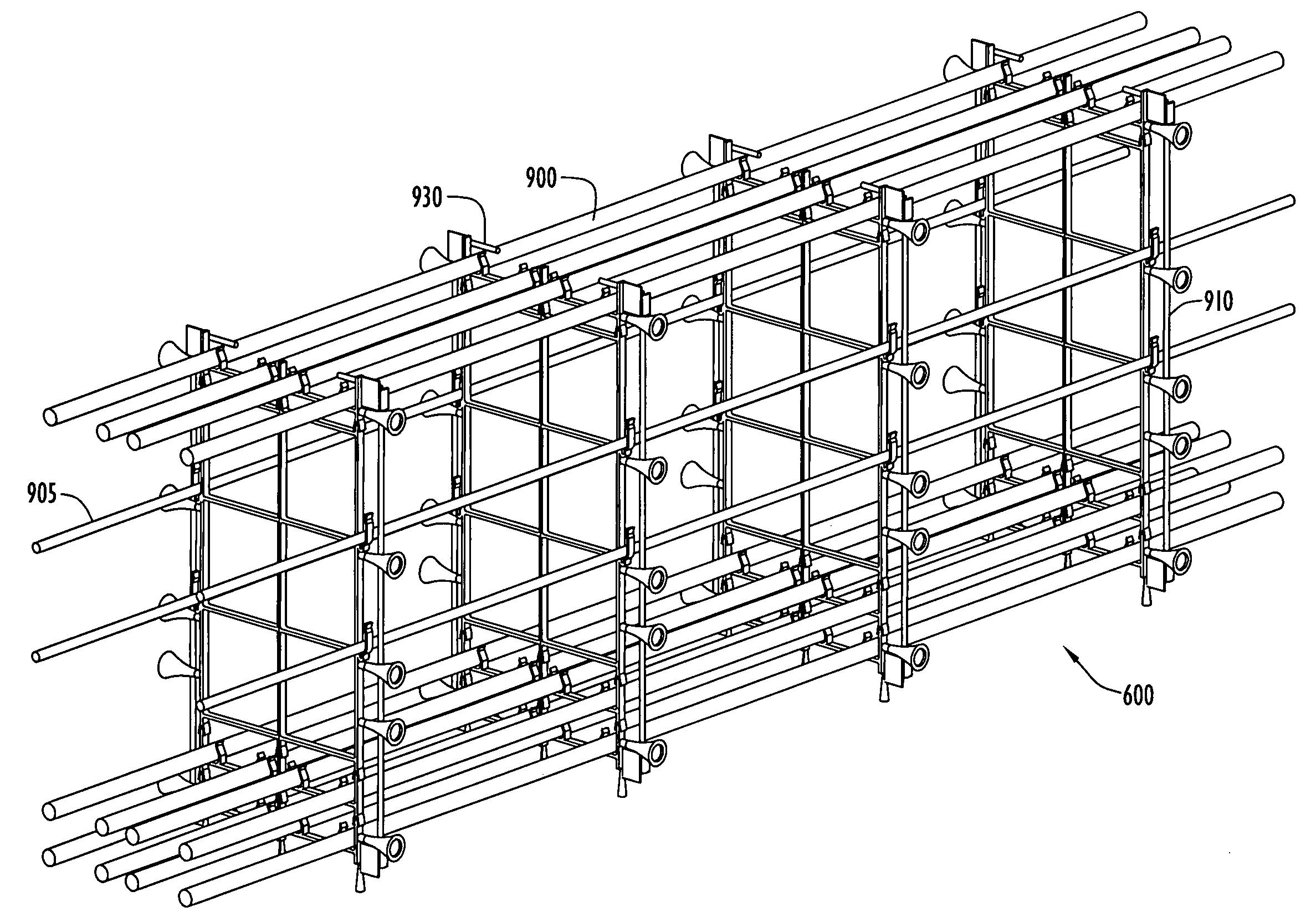
[0009]The present invention is directed toward a rebar support assembly utilized in the formation of cast-in-situ and precast structural elements and, in particular, in the formation concrete beams. The support assembly may include a frame having chair portion, a stirrup portion, an intermediate portion, and/or a header portion. Each portion may include one or more rebar receptacles designed to support a segment of reinforcement bar in a predetermined locati

Problems solved by technology

Concrete, while possessing strong compressive strength, is subject to tensile forces that, over the life of the beam, results in beam deflection or creep.
Conventional rebar support systems suffer from several drawbacks.
This process is very labor intensive.
Another problem with conventional rebar support systems is that when the main reinforcing rebar is wound onto the metal stirrup, the integrity of the wound rebar is completely dependent on the skill of the worker winding the binding wire, yielding a winding junction that is non-repeatable and lacking uniformity from job to job.
In addition, the wound wire configuration risks the dislocation of rebar if the metal wires are unwound or broken during the process of pouring concrete.
Still another disadvantage of metal wire stirrups is the rusting / oxidation of the binding wire.
Since the binding wire tends to extend from the resulting concrete beam, the wire is exposed to the environment, risking the oxidation of the wire over time.

Method used


Image

  • Rebar Support Assembly
  • Rebar Support Assembly
  • Rebar Support Assembly

Examples


Embodiment Construction

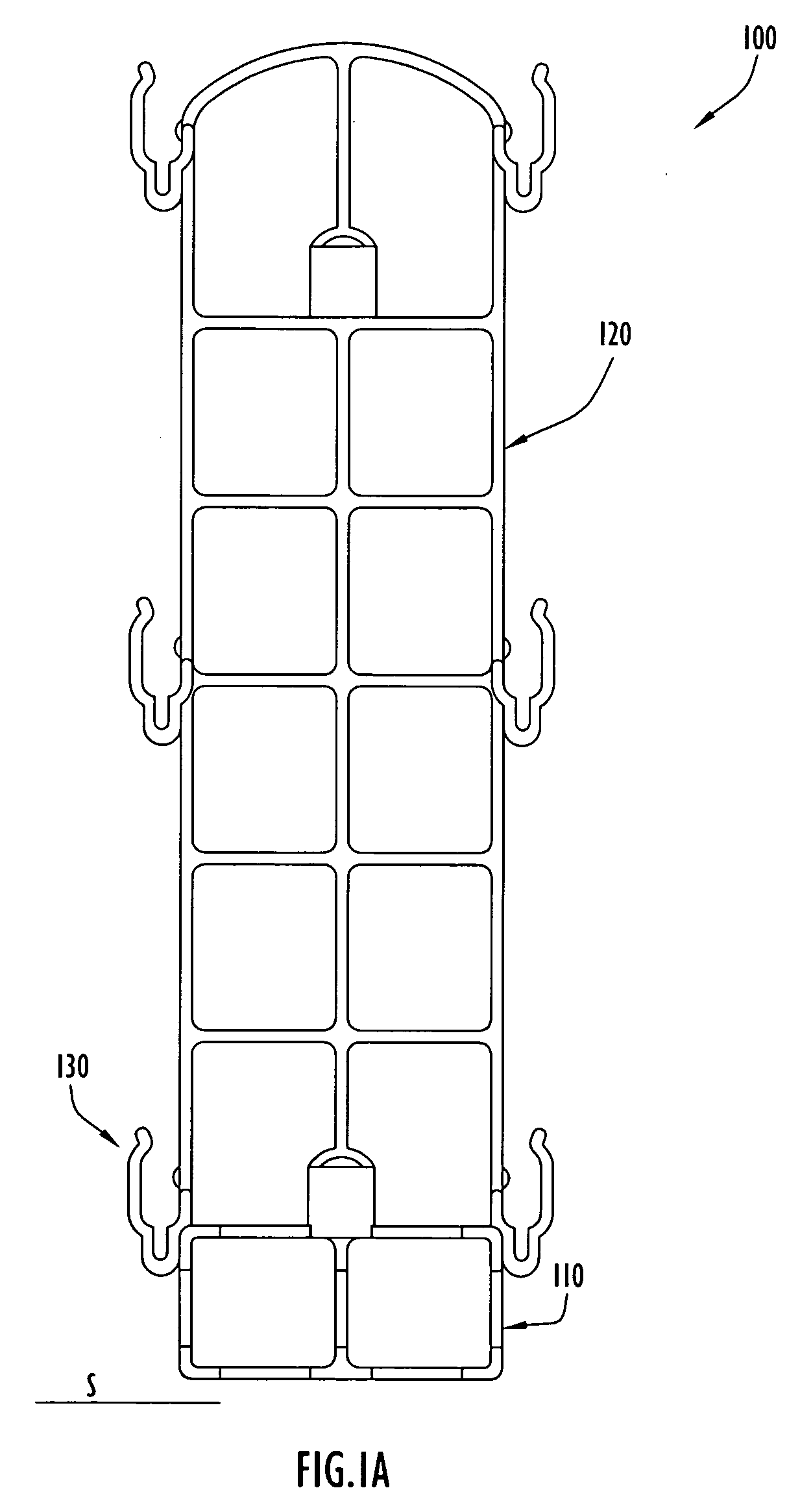
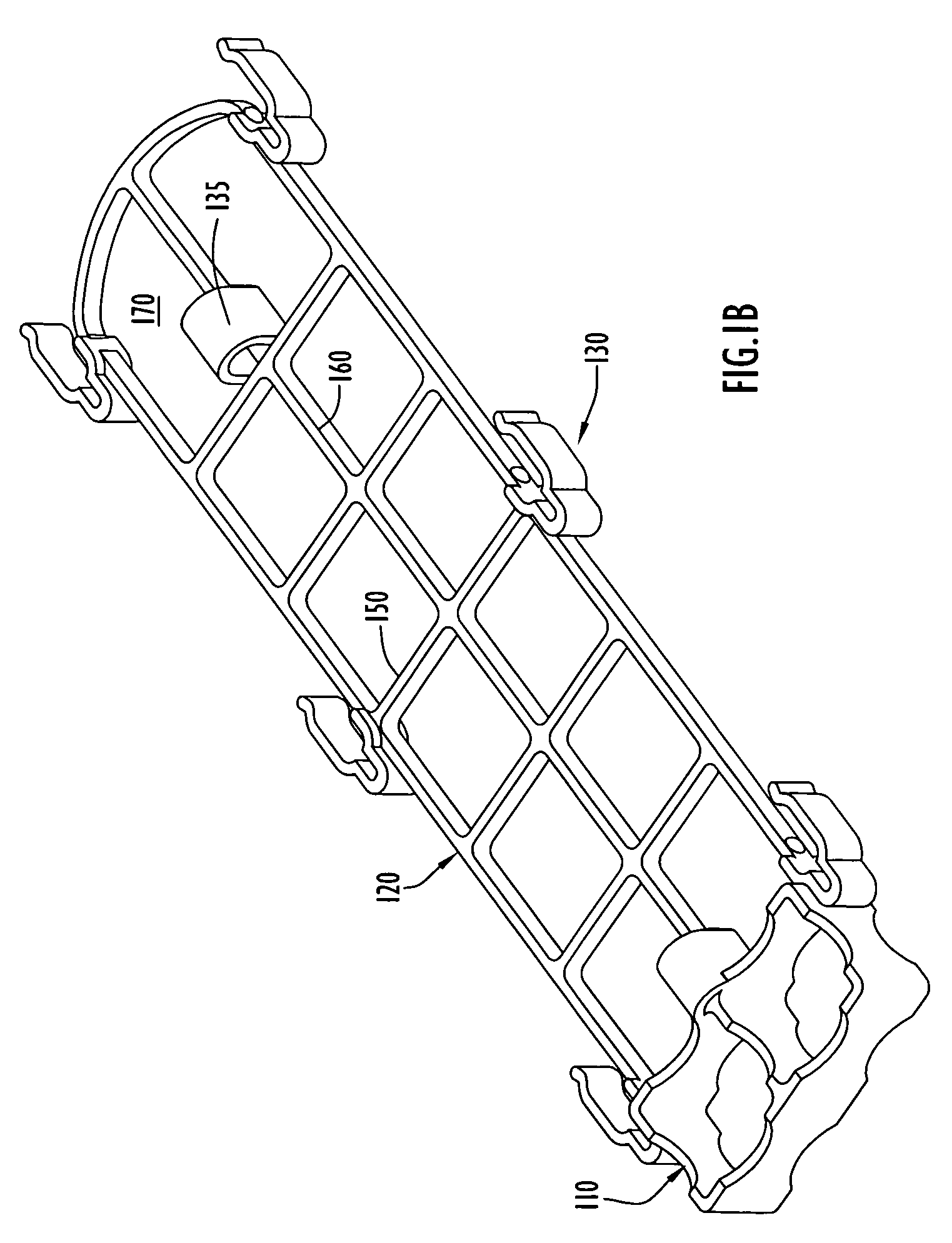
[0030]FIGS. 1A and 1B illustrate a rebar support assembly in accordance with an embodiment of the invention. As illustrated, the support assembly 100 may be in the form of a frame having a unitary structure including a chair portion 110, a body or cage portion 120, and one or more receptacles 130. The chair portion 110 engages a supporting surface S (e.g., the ground, concrete pour area, formwork, etc.), elevating the cage portion 120 and receptacles 130 above the surface. The chair portion 110 includes at least one aperture to permit the flow of concrete therethrough. As seen best in FIG. 2, the chair portion 110 may include an exterior wall 200 defining an open area that is divided by an interior wall 210 to create a first flow-through or channel 220 and second flow-through or channel 230. The chair walls 200, 210 may be reinforced with multiple radii, cross-, and T-shaped junctions to maximize strength and yield necessary stability while snapping in the main reinforcement bar dur...


PUM


Abstract

The present invention is directed toward a rebar support assembly utilized in structural construction beams. The assembly may include a frame having chair portion, a cage portion, an intermediate portion, and / or a header portion. Each portion may include one or more rebar receptacles designed to support a segment of reinforcement bar in a predetermined location and orientation. For example, the receptacles may be configured to orient the rebar in a generally horizontal and / or a generally vertical position. The assembly may be configured as a unitary structure, or may be modular to customize the rebar support for a job site. In use, the assembly is positioned on the supporting surface of the concrete pour area and rebar segments are coupled to the receptacles. Concrete is then poured over / around the assembly.

Description

CROSS REFERENCE TO RELATED APPLICATIONS[0001]This application is a non-provisional application of provisional application No. 60 / 912,524, entitled “Rebar Support System” and filed on 18 Apr. 2007, the disclosure of which is hereby incorporated by reference in its entirety.FIELD OF THE INVENTION[0002]The present invention is directed toward a rebar support assembly and, in particular, to a rebar support assembly for reinforced concrete beams.BACKGROUND OF THE INVENTION[0003]Concrete beams are structural elements typically utilized to transmit tributary loads from floor slabs to vertical supporting columns or walls, as well as to transmit the weight of a super-structure to the supporting soil. Concrete, while possessing strong compressive strength, is subject to tensile forces that, over the life of the beam, results in beam deflection or creep. Reinforcing the beam accommodates for tensile stresses, minimizing creep as well as minimizing the width of any cracks that develop during th...

Claims


Application Information

Patent Timeline
IPC IPC(8): E04C5/16
CPCE04C5/163E04C5/205E04C5/168
Inventor GARZA, FRANCISCO L.VERDI, MARIOGALAL, KHALED ELMANDOOH
Owner 3GM PRODS
Learn More